How to Install an Alarm.com VDB770

Use this guide to assist with the installation of your VDB770 doorbell camera using a Digital or Mechanical Chime.

Pre-installation checklist

  • ADC-VDB770 and included accessories
  • Wire crimping tool
  • Wi-Fi connection to broadband (Cable, DSL, or Fiber Optic) internet
  • A computer, tablet, or smartphone with Wi-Fi is required if the router does not have the Wi-Fi Protected Setup (WPS) feature
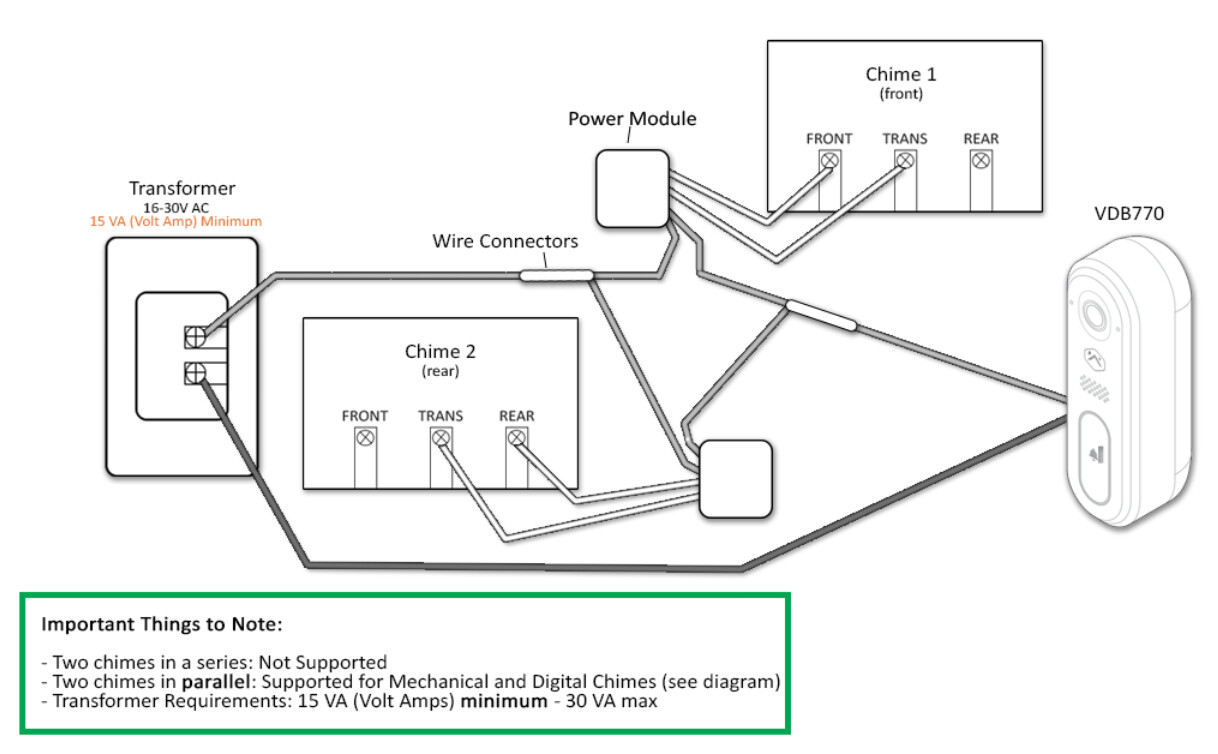
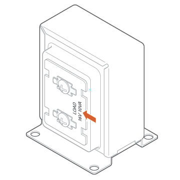
  • Verify that your transformer meets the minimum voltage of 16 VAC and minimum power of 10 VA; specifications are often written directly on the transformer
  • A compatible chime, Digital or Mechanical.
  • Video Analytics is required,:
    • Video Doorbell only add on, or
    • Surety Complete service plan

VDB770_transformer_preview

Installation

Install the power module
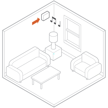
  1. Verify that the electricity is turned off at the transformer before installing the power module. Locate your chime box and remove the cover.
    VDB770_chime_box_preview
  2. Note the existing wire connections (e.g., the wires may be connected to the Front or Rear doorbell terminal); you will want to connect to the same doorbell terminal in the next step. Loosen the screws on the chime associated with the transformer and doorbell. Set the wires aside.
  3. Take the power module and hook the curved white wires onto the screw terminals (it does not matter which white wire goes to the transformer terminal and which goes to the doorbell terminal). Tighten the screws.
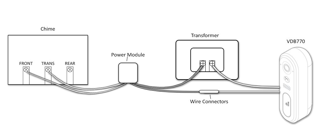
  4. Using a crimp tool and the wire connectors provided, connect the wires that were set aside to the straight gray wires of the power module.
  5. Affix the power module to the side of the chime using the included adhesive. Replace the chime cover.

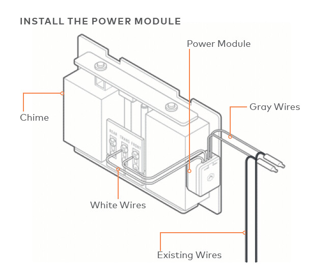
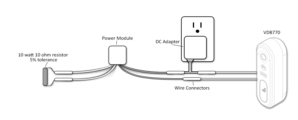
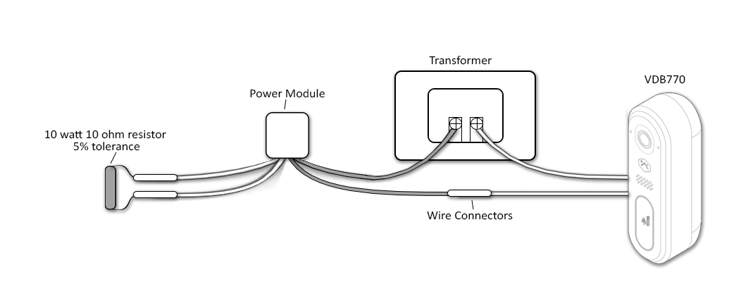
  • Note : The power module must be used in every installation regardless of the chime type. The power module is used to prevent the chime from buzzing or humming, and it helps ensure sufficient power is provided to the Alarm.com Video Doorbell.

Install the Alarm.com Video Doorbell

  1. Remove the existing doorbell from the wall and disconnect the wires. Secure the wires so that they can be connected in a later step.

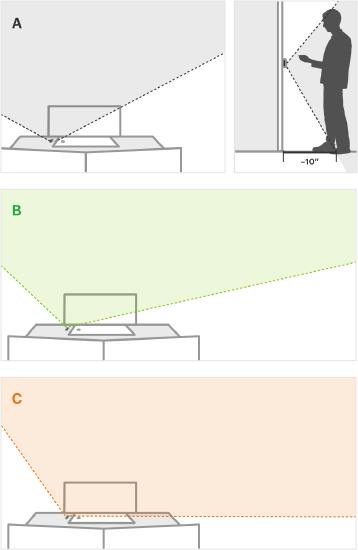
  2. At the installation location, an angled mounting bracket can be used to modify the field of view. Choose a mounting bracket type best suited for your installation setup. Installation scenarios corresponding to mounting bracket types A, B, and C are provided below to guide your decision.

  1. Thread the existing wires through the mounting bracket. Install the mounting bracket to the wall using the included wall screws (and anchors, if needed for the mounting surface).

  1. Thread the wire extenders through the backplate. Remove the wire caps

  2. Crimp the two wires coming through the backplate to the existing wires threaded through the mounting bracket.

  3. Install the doorbell backplate to the mounting bracket using the included machine screws.

  4. Attach the doorbell to the backplate by aligning and pushing together until it clicks into place and the connection is well sealed.

  5. Turn the electricity back on. Check that the doorbell camera’s light is flashing white after the boot process is complete.

    • Note : If the LED is solid red after the boot-up process is complete, press and hold the main button until the light begins alternating green and red.

Wire the ADC-VDB770 without a chime

The ADC-VDB770 can be powered without a chime using either of the following:

  • DC adapter with a power rating of 15-30V DC, 8W minimum
  • AC transformer with a power rating of 16-30V AC, 10-30VA.

Important: This chimeless configuration requires a resistor rated at 10 Watts 10 Ohms with 5% tolerance.

To wire the ADC-VDB770 without a chime using a DC adapter

  1. On the power module, attach the white wires interchangeably to a resistor (10 Watts 10 Ohms with 5% tolerance).
  2. Attach the gray wires interchangeably to a DC transformer and the ADC-VDB770.
  3. On the ADC-VDB770, attach the remaining wire to the transformer.

To wire the ADC-VDB770 without a chime using an AC transformer:

  1. On the power module, attach the white wires interchangeably to a resistor (10 Watts 10 Ohms with 5% tolerance).
  2. Attach the gray wires interchangeably to an AC transformer and the ADC-VDB770.
  3. On the ADC-VDB770, attach the remaining wire to the transformer.

The Video Doorbell Wall Power Supply Kit (ADC-VDBA-PSU-PD) has separate wiring instructions, see below.

The Video Doorbell Wall Power Supply Kit (ADC-VDBA-PSU-DC) is a DC plug-in power supply rated at 16V, 1.25A (20W). The Video Doorbell Wall Power Supply Kit is designed to easily power the ADC-VDB770 when not using an existing chime circuit. This supply can be used for installations where there is no existing wiring or where the existing setup is incompatible.

Important: The Wall Power Supply Kit should only be installed when no wired chime is used in the circuit.

Installation and wiring

Required materials

  • A 10 W / 10 Ohm resistor (or flameproof 5W / 3.9 Ohm resistor without a power module)
  • Wires for the power supply

Power module installed

No power module


Caution : Power will run through the resistor at all times using this configuration. You must use a flameproof resistor and ensure it is thermally isolated in the installation.

Connect the ADC-VDB770 to the network

AP Mode (recommended)
  1. The camera is in Access Point (AP) mode when the button LED is blinking white. If necessary, access AP mode by holding down the doorbell button for 35-40s and release when the LED turns to blinking white.
  2. Using a Wi-Fi-capable device (e.g., smartphone or computer), find and connect to the camera’s network; the SSID should have the format ADC-VDB770 (XX:YY:ZZ) where XX:YY:ZZ is the last 6 characters of the MAC address, which is printed on the included reference card.
  3. On the same device, open a web browser and enter http://vdb770install or 192.168.1.1 in the web address field. Follow the on-screen instructions to add the ADC-VDB770 to the Wi-Fi network. Verify the LED turns solid green, indicating the connection is complete.
WPS Mode (alternate)

Note: Use WPS mode if you have easy access to the Wi-Fi router and the router has the WPS feature enabled. Note that some Internet Service Providers disable the WPS feature on customer routers. AP mode is the most reliable method for installing this device.

  1. After the boot process is complete (the camera’s LED will be blinking white), hold down the doorbell button for 30-35s and release when the LED begins to blink blue.
  2. Activate WPS Mode on the router. The router will begin to connect to the Wi-Fi network. Verify the LED turns to solid green, indicating the connection is complete.
Enroll the Video Doorbell to the account
  1. Add the device to the account by using the Alarm.com Mobile App, or by using a web browser and entering the following web address: www.alarm.com/addcamera.
  2. Select the Video Doorbell from the video device list or enter in its MAC address to begin adding the device. The device’s MAC address is located on the included reference card.
  3. Follow the on-screen instructions to finish adding the device

Wire the ADC-VDB770 to two chimes

The ADC-VDB770 can support up to two digital or mechanical chimes simultaneously by using two power modules. The chimes themselves must be wired in parallel rather than in a series.

  1. On the first power module, attach the white wires interchangeably to the FRONT and TRANS terminals on the chime.
  2. On the second power module, attach the white wires interchangeably to the REAR and TRANS terminals on the chime.
  3. Attach one of each of the power modules to the transformer using a wire connector.
  4. Attach one of each of the power modules to the ADC-VDB770 using a wire connector.
  5. On the ADC-VDB770, attach the remaining wire to the transformer.

Setting Up Rules and Notifications for the VDB770

Troubleshooting