Alarm.com Smart Thermostat ADC-T2000 - Installation Guide

Energy_Star_Smart_Thermostat_T2000

Installation precautions

  • Before installing or servicing the thermostat, turn off power to the system at the circuit breaker.
  • Leave power off until the thermostat has finished installing or servicing.
  • Shorting the electric terminals at the control on the heating or cooling system may damage the thermostat. Do not test the system this way.
  • Follow all local codes and ordinances for wiring the system.
  • This thermostat should only be powered by 4 AA alkaline batteries and/or a listed class 2 power supply at 24 VAC (C-Wire or wall transformer).
  • An amperage higher than 1 amp to each thermostat relay load may cause damage to the thermostat.
  • Verify that the system is 24 VAC.

Important : If the old system is labeled as 120 or 240 volts or has wire nuts, the system is high voltage. Do not install the thermostat to a high voltage system. Contact a local HVAC professional for additional assistance.

In the box

In_the_T2000_box

Recommended tools

Thermostat overview

T2000_overview

Buttons

Icon Function
UP Adjust target temperature up.
MODE Change thermostat between HEAT, COOL, AUTO, EMER and OFF modes.
DOWN Adjust target temperature down. Also used to include and exclude from the network.

Modes

Icon Function
HEAT Will activate the heating system.
COOL Will activate the air conditioner.
Auto Will select either the HEAT or COOL mode automatically.
EMER For use with heat pumps only. Will bypass the heat pump and enable the auxiliary/emergency heat.
OFF The system will not heat or cool.

Display

Icon Function
HEAT Illuminated in HEAT, EMER or AUTO mode.
COOL Illuminated in COOL or AUTO mode.
RADIO Illuminated during the wireless configuration.

Installation - Preparation

If replacing an old thermostat, the new thermostat can be mounted in its place. If a new location is desired it will be necessary to move the wiring.

New installations and relocation should follow the accompanying guidelines to ensure the most accurate temperature reading and ease of use.

  • Mount thermostat on an inside wall, approximately 5 feet (1.5 meters) above the floor in a frequently used room.
  • Do not install in locations near appliances or devices that affect the local temperature such as televisions, lamps, or dryers.
  • Avoid areas that are exposed to large temperature variances (e.g., direct sunlight, near an AC unit, above or below auxiliary heat and air vents, and drafts from windows).
  • Be aware of what is on the other side of the wall where the thermostat is being installed. Do not install on walls adjacent to unheated rooms, stoves, or housing hot water pipes.
  • Damp areas will not only affect the humidity reading of the thermostat, but could lead to corrosion and shorten the life of the thermostat.
  • Install in a location with good air circulation. Stagnant air will not accurately reflect the rate of temperature change in the room.
  • Avoid areas behind open doors, corners, and alcoves.
  • Wait until construction and painting are finished before installing.

The existing thermostat

  1. Test the system.
    • Verify that the heating and/or cooling system is operating properly before attempting to install the new thermostat.
    • Caution : Do not test the system by shorting electric terminals at the furnace or air conditioner. This may damage the thermostat.
  2. Turn the power off.
    • Turn all heating and cooling systems off. This can be done at the circuit breaker.
    • Caution : Do not remove the existing thermostat until power has been turned off at the circuit breaker.

Once power to both the heating and cooling systems is off, follow these steps:

  1. Remove thermostat cover.

    • Remove the cover from the existing thermostat. Do not disconnect the wires yet.
    • Important: Take a picture of the wires before detaching them from the existing thermostat for future reference.
  2. Label all existing wires.

    • Label all existing wires, one at a time, with the labels provided.
    • Make sure the wires are labeled correctly. If there is an unidentified wire, it may be necessary to identify the wire where it connects to the heating or air conditioning equipment.
    • Important : Take another picture of the wires to document connections for easy reference. Do not disconnect wires before labeling them.
      Label_all_existing_wires
    • Caution : Wiring can vary for each manufacturer. Label all wiring before removing it from the existing thermostat.
    • Disconnect all of the wires and remove the existing thermostat.
    • Important: Remember to secure the wires so they don’t fall into the wall.

Prepare the wires

Follow these guidelines for safe and secure wire connections:

  • Verify the wires are solid core and have proper gauge between 18-24 AWG
  • Verify the wires have exposed straight ends about 1/8” long
  • Only one wire should be inserted into each terminal on the thermostat

Caution : Verify that the system is 24 VAC. If the old system is labeled as 120 or 240 volts or has wire nuts, the system is high voltage. Do not install the thermostat to a high voltage system. Contact a local HVAC professional for additional voltage assistance.

Installation - Install the new thermostat

Install the back plate

Use the bubble level provided on the back plate as a guide. Mark where the screws will go with a pencil through the screw holes on the back plate. Verify the top of the back plate is facing up.

Note: If necessary, use the trim plate to cover up any marks or holes left from the old thermostat. Attach the trim plate before securing the back plate to the wall. Drill holes with 3/16” drill bit to tap in the drywall anchors for added support.

Wire the new thermostat

Reconnect the wires to the new thermostat and indicate the connected wires with a pencil in the image below. This information will be needed when configuring the thermostat.
Wire_new_thermostat

Caution : If there are extra wires, do not install them in the new thermostat. Please contact a local HVAC professional for additional assistance.

  • If there is an R wire, connect it to RH.
  • If there are both RH and RC wires, remove the black jumper in the lower left corner of the backplate terminal board with needlenose pliers, and attach wires to both RH and RC terminals.
    T2000_jumpers
  • Z can be used for W3, H, DH, O/B Zoning, or Ventilation.

Terminal designations

Conventional system

Terminal Description
RC Cooling power
RH Heating power
Z Configurable W3, H, DH, O/B Zoning, or Ventilation
W Heat stage 1
W2 Heat stage 2
W3 Heat stage 3
C Common wire from secondary side of heating transformer (if 2 transformers)
Y Cool stage 1
Y2 Cool stage 2
G Fan
H Whole home humidifier
DH Whole home dehumidifier
O/B Energized in cool mode

Heat pump

Terminal Description
RC Cooling power
RH Heating power
Z Configurable W3, H, DH, O/B Zoning, or Ventilation
W Aux stage 1
W2 Aux stage 2
W3 Aux stage 3
C Common wire from secondary side of cooling transformer
Y Pump stage 1
Y2 Pump stage 2
G Fan relay
H Whole home humidifier
DH Whole home dehumidifier
O/B Reversing valve

Insert batteries into the thermostat

Insert_batteries

The thermostat can be powered by battery and/or 24 VAC. Even when powered by 24 VAC, it is still recommended to insert batteries as a backup in case the C wire fails. This also prevents low battery trouble conditions.

Note: If a wall transformer is used to power the thermostat, connect between C and RH. The system must be either heat-only or cool-only when using a wall transformer, as the transformer would wire into one of the R terminals (Rc or Rh depending on what is open) and the C terminal with the jumper removed.

Ensure the batteries are installed following the specified polarity markings on the thermostat.

Caution: Special Battery Warning

  • Always replace the batteries as soon as they have low battery levels, indicated by “LOW” then “BATT” flashing on the display. If the batteries drain, the thermostat could leave the HVAC system on or off, overheating or freezing the home.
  • Always replace the batteries at least once a year. This will protect the thermostat from damage and corrosion by leaking batteries.
  • If the home is unoccupied for a month or more, such as vacation homes, replace the batteries as a preventive measure against battery failure while away.
  • Always use new batteries as replacements.

Attach the body and back plate

Verify that any excess wire is tucked back into the wall to allow room for the thermostat to sit flush against the back plate.

Press the thermostat body firmly into the back plate mounted to the wall. Ensure that the pins on the body are correctly aligned with the header attached to the terminal board on the back plate. Failure to do so could cause damage to the thermostat.
Install_body_to_back_plate

Turn the power on

Restore power to all the heating and cooling systems. This can be done at the circuit breaker.
Turn_power_on

Installation - Connect T2000 to the Z-Wave Network

Configure the system

The thermostat configuration will be done on the online account. Here it is possible to configure the parameters of the system, such as: Heat Pump or Normal, number of heat and cool stages, heating fuel, calibration temperature, and configurable terminal (Z). Using the online account, the thermostat configuration must be entered. Refer to wiring diagram above for the appropriate diagrams when setting up the thermostat.

While the default settings will be sufficient in most cases, there is also the option to change advanced configuration settings, such as: Swing, Differential, Recovery Settings, Fan Circulation Period and Duty Cycle, Maximum Set Points, Minimum Set Points and Thermostat Lock.

Caution : Use caution when changing advanced configuration settings. These configuration settings should only be changed by those familiar with heating and cooling systems’ parameters. Contact a local HVAC professional for help.

Check the system

Caution : Do not test the AC during cold weather or heat during hot weather. Wait for mild weather to fully test the system.

To check heating:

  1. Press MODE to select HEAT mode.
  2. Press UP to raise the set point above room temperature.
  3. Wait 5 minutes for the system to turn on.
  4. After verifying the heating system is working, return the set point to the desired temperature.

To check cooling:

  1. Press MODE to select COOL mode.
  2. Press DOWNto lower the set point below room temperature.
  3. Wait 5 minutes for the system to turn on.
  4. After verifying the cooling system is working, return the set point to the desired temperature.

Manual configuration of HVAC system on thermostat

The system type listed in the table below can be physically set on the thermostat by doing the following:

  1. Put the thermostat in OFF mode.
  2. Press and hold UP for 5 seconds until the display shows a version number.
  3. Press and hold UP again for 5 seconds until the display shows your HVAC setup.
  4. Press UP or DOWN to select the thermostat configuration from the table below.
  5. Press MODE to confirm the selection.
Configuration System type Description/Note
NORM Normal 2-heat 2-cool system Normal electric heating system, thermostat turns on fan with heat. Two or fewer stages of heating and of cooling are allowed.
FOSL Fossil 2-heat 2-cool system (for hydronic heat w/no fan) Normal fossil heating system, thermostat does not turn on the fan using the G wire when heating. Gas furnace or hydronic usually.
PUMP Heat pump (O terminal) Heat pump using O in the O/B termina with two or fewer stages of electric aux heating.
PMPB Heat pump (B terminal) Heat pump using B in the O/B termina with two or fewer stages of electric aux heating.
DUAL Dual fuel system (O terminal) Heat pump with two or fewer stages of fossil aux heating using O in the O/B terminal.
DULB Dual fuel system (B terminal) Heat pump with two or fewer stages of fossil aux heating using B in the O/B terminal.

System Operation

T2000_operation

  1. Press any button to wake the thermostat up.
  2. After waking, the display will show the current mode and room temperature.
  3. Press UP or DOWN once to display the current set point.
    • The mode icon HEAT or COOL will begin to pulse.
  4. Press UP or DOWN ​​​​again to adjust to the desired set point.
  5. Press MODE at any time to change the mode.
    • The modes are HEAT, COOL, AUTO, EMER, and OFF.
    • EMER mode is available for Heat Pump systems. Press and hold MODE while in Heat Mode to enter EMER.
    • When in EMER mode, the display will read EMER when the thermostat wakes up and the HEAT icon will be displayed. Changing the mode will leave EMER mode.
  • In AUTO, the brighter icon will indicate which set point is currently displayed and active HEAT or COOL.
  • After 5 seconds the display will return to the current room temperature. The mode icon will become solid to indicate this. If powered by the “C” wire, the thermostat display will remain lit. If the thermostat is running on battery power only, the display will turn off after 5 seconds to conserve energy. The thermostat will continue to operate while the display is off.

Additional Information

Changing the batteries

Humidity control

The thermostat can adjust the humidity level in a home by directly controlling an external humidifier, dehumidifier, or by using the cooling system to dehumidify. For an external humidifier or dehumidifier, the thermostat must be configured to use the Z terminal.

For controlling dehumidification by the cooling system, a cooling system must be present without an external dehumidifier. In this case, the thermostat will extend your cooling cycles in an attempt to reach your dehumidification setpoint.

To change humidification/dehumidification settings refer to the Alarm.com Website.

Ventilation

The thermostat can control a ventilation system (HRV, ERV, or air baffle) using the Z terminal. By default, the thermostat will operate the ventilation system for 15 minutes every hour. To change the ventilation settings, refer to the advanced configuration settings through the Alarm.com Website or mobile app.

Troubleshooting

Heating or cooling doesn’t turn on when the set point is above or below the room temperature

To prevent damaging the compressor, the thermostat inserts a delay when cycling the compressor.

If the system should be on and it’s not, then change the set point to be 2 degrees beyond the current set point and wait 5 minutes to see if the system turns on. If not, contact a local HVAC professional.

Heat pump is “Cooling when it should be heating” or “Heating when it should be cooling”

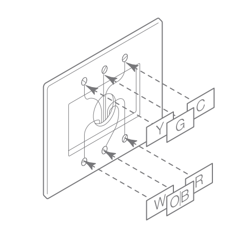
Some heat pumps use the O terminal, while others use the B terminal for their reversing valve. Your heat pump may be the opposite type from how the thermostat is wired.

Try switching the O/B configuration setting through the online account. Contact a local HVAC professional for further help with this issue.

Batteries drain quickly

If a thermostat is included using a “C” Wire, that information is saved in the network and cannot be changed unless excluded and included again without a “C” Wire connected. The same applies to thermostats included on battery power.

If a device is added using the “C” Wire, the Z-Wave communication never sleeps, and the thermostat will act as a repeater, sending messages for other devices as well. If the “C” Wire was removed, this kind of behavior will drain the batteries very quickly

Verify the “C” Wire connection is still intact.

HVAC system is not holding the temperature

If the HVAC system is not consistently holding the temperature, it maybe be a wiring or other HVAC-related issue. Contact an HVAC professional.

The A/C is not working

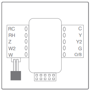
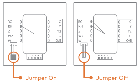
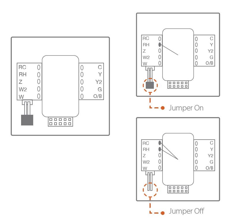
The R wire could be plugged into RH, and the jumper was removed, so Y and G are not getting power.

The heat is not working

The R wire could be plugged into RC, and the jumper was removed, so W is not getting power.

The heat works, but I cannot control the fan

The R wire could be plugged into RH, and the jumper was removed, so G is not getting power.

Both RC and RH were present, and the jumper was not removed, now the system does not work

An HVAC technician will be needed to fix the blown fuse or transformer.

Factory Reset ADC-T2000

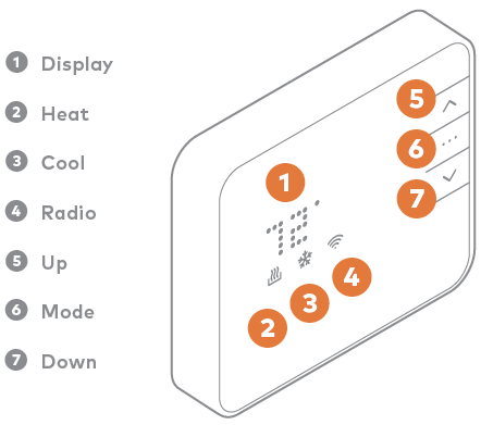
  1. Press [. . .] to put the thermostat into Off mode. When the thermostat is in Off mode, no symbols are lit below the temperature display.
  2. Once in Off mode, press and hold Up on the Smart Thermostat until a version displays. The version number does not matter for this process.
  3. Once the version displays, press and hold Down on the Smart Thermostat until RST displays on the thermostat.
  4. When RST clears from the thermostat display, the thermostat is reset to factory default configurations.

Important : If Thermostat Lock is enabled, the thermostat will not respond to button presses until Thermostat Lock is disabled. If the Security Panel (or other Z-Wave Controller) becomes unresponsive, or if the thermostat is not enrolled onto an active Alarm.com account, a full reboot (i.e., removing AC and battery power) of the thermostat will bypass the local thermostat lock on any Alarm.com Smart Thermostat with Z-Wave version 1.2+.