Honeywell/ADEMCO Vista System Enhancement Module (SEM) Compatibility and Setup Guide

If you have a Honeywell Vista series panel, you may be able to connect it to Alarm.com using the System Enhancement Module or SEM.

This guide will cover how to determine if your Honeywell/ADEMCO Vista panel is compatible with the Alarm.com SEM and how to connect it to the SEM if it is.

Is my Vista Panel Compatible?

Supported

The SEM is compatible with the Honeywell/ADEMCO VISTA:

  • 10P
  • 15P
  • 20P
  • 21 IP

Panels should work as long as they were manufactured in 2005 or later and version 3.1+.

You can confirm if your panel is compatible by checking the PROM chip located on the panel control board.


In this example the PROM chip indicates that the panel is a Vista 15P (from WA15P on the first line of the sticker) and was made in 2013 (from the bottom line of the sticker).

Panel variants
The following table displays some of the variants of each Vista panel type compatible with the SEM:

Honeywell Vista-10P Honeywell Vista-15P Honeywell Vista 20-P
VISTA-10PSIA VISTA-15PSIA VISTA-20PSIA
First Alert FA130CP First Alert FA148CP First Alert FA168CPS
First Alert FA130CPSIA First Alert FA148CPSIA First Alert FA168CPSSIA

Unsupported Panel Models

The following panels are common Honeywell/ADEMCO Vista models that are not supported by the SEM.

  • Vista 20
  • Vista 20se (Also known as Safewatch Pro 2000)
  • Vista 20hwse
  • Vista 15se
  • Vista 10
  • Vista 10se
  • Via-30pse
  • Vista 32p (all 32 / 32p / 32fb variants)
  • First Alert FA145C
  • Vista 50p (all 50p variants)
  • Vista 128p (all 128 / 128p / 128fb variants)
  • Any Honeywell Lynx series panel

Should you have one of these panels it would need to be replaced in order to utilize service with Alarm.com/Surety

Pre-Connection Checklist

This section of the guide covers how to setup the SEM once you have determined that it is compatible with your Vista panel.

Prior to installing the SEM and getting connected to your Alarm.com account, there are a couple steps that must be taken:

  • Get access to your Vista panel’s Installer Code
  • Enable keypad 8 device Address 23

The Installer Code

The SEM is a bit different when it comes to Alarm.com compatibility. It requires that the user have access to their Vista panel’s Installer Code prior to the creation of their Alarm.com account. This code is necessary as Alarm.com uses this code to access panel programming and read information stored on the panel.

The following video shows how to access programming without the current installer code. The installer code can then be reset to that of your choosing.

Enable keypad 8 device Address 23

The SEM communicates with the VISTA panel as if it is a keypad. By default, the SEM will use Keypad 8 Device Address 23 to communicate. Address 23 must be enabled via panel programming. If the correct keypad address is not enabled, the panel and module cannot communicate properly. This is one of the biggest mistakes when it comes to setting up the SEM, so make sure you follow this step beforehand.

To verify keypad 8 device address 23 using the keypad:

  1. Enter the installer code.
  2. Press [800] to enter programming.
  3. Press [#][196] to go to the keypad options field.
  4. It should show 01 , then 00 to indicate it is enabled.
    • If it is not enabled, enable it using the steps below.
    • If address 23 is already in use, see below.
  5. Press [*][99] to exit programming.

SEM_Verify_196

To enable keypad 8 device address 23:

  1. Enter the installer code.
  2. Press [800] to enter programming.
  3. Press [*][196] to edit keypad address 23.
  4. Press [1][0] to enable the keypad address. The keypad should beep to indicate it was saved.
  5. It should show 01 , then 00 to indicate it is enabled.
  6. Press [*][99] to exit programming.

Click Here For Animation

To enable a different keypad address (if address 23 is in use):

In most cases, Address 23 will be available. If another keypad is already connected to Address 23, a different keypad address must be selected for the SEM.

  1. Identify an available keypad address.
  2. Enable the address at the keypad by entering the corresponding VISTA programming command using the Keypad address table below.
  3. Power the system off.
  4. Adjust the SEM DIP switches on the SEM to match the corresponding keypad address using the Keypad address table
  5. Power the system on. Verify a zone scan initiates upon power up.

Keypad Address Table

|Keypad Address | DIP Switch Setting | VISTA Programming Menu |
|—|—|—|—|—|
| 17 | None—all OFF | *190 |
| 18 | Switch 4 ON, others OFF |*191 |
| 19 | Switch 3 ON, others OFF | *192 |
| 20 | Switch 3 and 4 ON, others OFF | *193 |
| 21 | Switch 2 ON, others OFF |*194 |
| 22 | Switch 2 and 4 ON, others OFF | *195 |
| 23 | Switch 2 and 3 ON, others OFF | *196 |

This section covers how to wire up the SEM to your Vista panel and then how to finalize the connection between the SEM and your Alarm.com account.

Note: Wiring the SEM and running the zone scan (below) should be done after your Alarm.com account has been created.

Wiring up the SEM

Disconnect power from the panel

Prior to disconnecting power from the Vista panel, first verify that the panel is disarmed.
Next, remove panel AC power and disconnect the backup battery.

Caution : This is necessary to prevent damaging the panel or module while making wiring connections.

Mount the SEM

Caution : You must be free of static electricity before handling electronic components. Touch a grounded metal surface before touching
the circuit board.

  1. Press down on the bottom tabs of the enclosure cover to remove it and set it aside.

  2. Carefully remove the SEM circuit board by depressing the interior bottom tab.

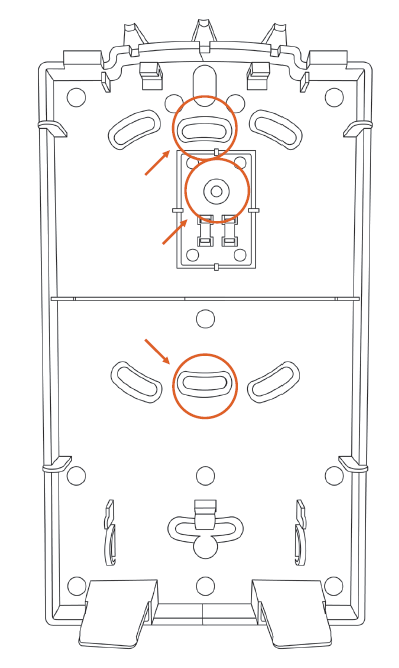
  3. Place the SEM back plate on the wall at the desired mounting location and mark the three mounting holes as shown below.

  4. Set the back plate aside and drill holes at the mounting locations.

  5. Use wall anchors where studs are not present and secure the back plate to the wall with the enclosed screws.

  6. Insert the SEM circuit board back into the back plate.

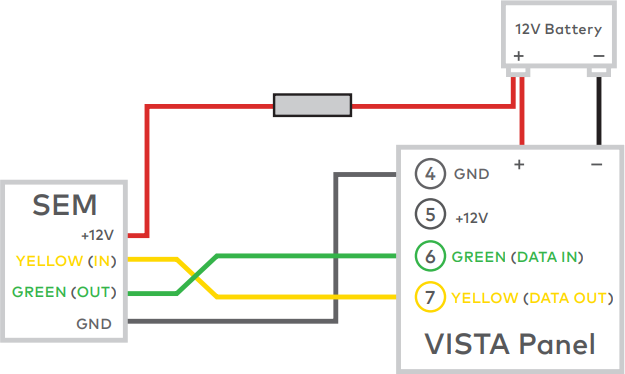
Wire the SEM to the panel

Alarm.com states that • Four-conductor, 22-gauge or larger stranded wire is needed.

Caution : Verify panel AC power is removed and the backup battery is disconnected when wiring the SEM.

Connect-3

  • Connect panel terminal 4 (GND) to SEM GND.
  • Connect panel terminal 6 (GREEN: DATA IN FROM KEYPAD) to GREEN (OUT).
  • Connect panel terminal 7 (YELLOW: KEYPAD DATA OUT) to YELLOW (IN).
  • Use the included red cable with the two prong battery connector to connect the battery to both the SEM and the panel. For a power limited circuit, ensure the fuse is inside the Vista panel.

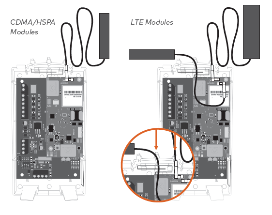
Once wiring is complete, route the antennas outside of the enclosure, away from the SEM, and replace the enclosure cover.

Note : The antennas should be routed through the second and third channel openings at the top of the enclosure as shown in the following images:

Connect-4

Dual-Path (Optional)

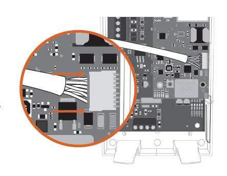
For Broadband Ethernet, connect the provided Ethernet Dongle to the connector on the SEM.

Connect the Ethernet cable to the provided Ethernet Dongle.

Connect-5

Power up the panel

Connect the backup battery and restore AC power to the panel. For the SEM to interact with the existing zones on the system, it must read them from the Vista panel. The SEM does a zone scan to read this information.

Additionally, the SEM will automatically set the panel settings needed for the SEM to communicate.

Connect-6

The zone scan will automatically begin after the panel is powered up. On the keypad, you will see a series of disarms and programming setting changes before seeing MODEM COMM on the screen. If you have a non-alpha keypad, the keypad will show CC instead of MODEM COMM.

Connect-7

When the zone scan is complete the keypad will display the home screen. This process takes less than three minutes. Now that the zone scan is complete, the Equipment list should be updated and the installer and master user codes should be synced with the SEM.

Note : If you do not see the MODEM COMM message appear on the keypad during zone scan and instead notice the keypad scrolling through each zone individually, the SEM is using an alternate zone scan method. Wait for the SEM to finish scanning and leave programming before interacting with the panel. Re-sync the panel master code with the SEM by changing the master code at the panel.