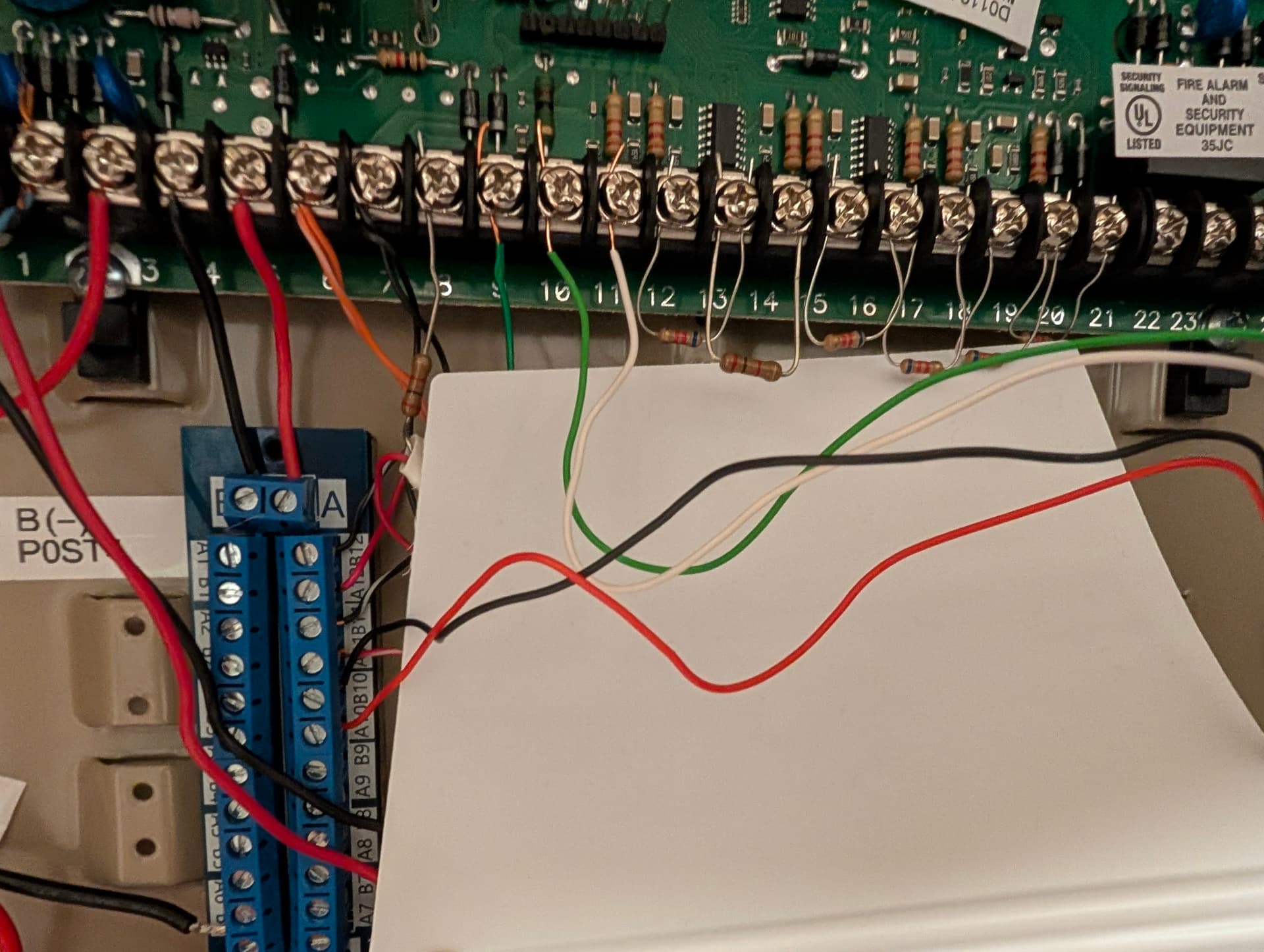
On my panel, I’ve added a terminal block to the PCB to so I wouldn’t have to have a bunch of cables all crammed together on terminal 5 on the panel; can I safely use one of the available terminals on my block instead of using the tap?
Yeah electrically it’s the same with your terminal block as if you had them all crammed into the one terminal. The only concern would be if you had too many devices (too much load) being powered by it,
That’s a good point about the load, I hadn’t even thought about that. Most of my sensors are wireless but I do have a wired siren, wired motion and maybe one other device.
I was just thinking of something after I wrote this question; if the +12vDC is wired directly to the battery and the panel has some power issue, then the could the SEM still monitor and report on the status of the panel?
I was just thinking of something after I wrote this question; if the +12vDC is wired directly to the battery and the panel has some power issue, then the could the SEM still monitor and report on the status of the panel?
Unless the GND is cut it would remain powered off the battery.
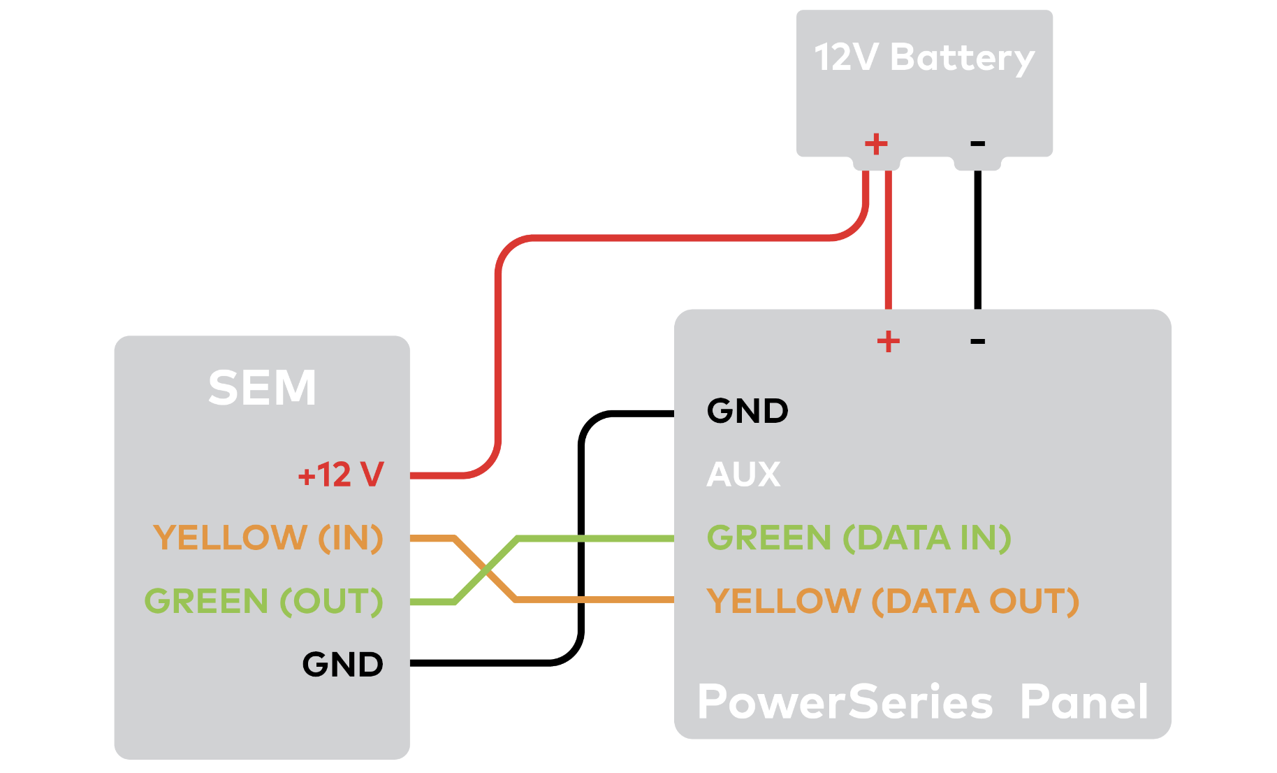
The SEM should only be powered per the installation manual, with + wire lead to the battery. Here is the diagram below:
The PCB looks to be printed off center from the terminal block, but it looks like the wiring should be (from left to right) Y (OUT), G (IN), GND, +12v. Can someone confirm that this is correct: