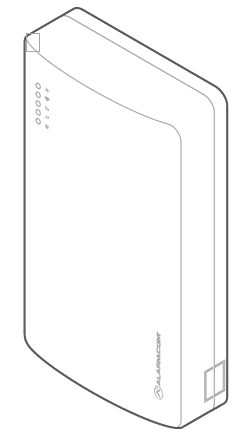
Alarm.com Dual-Path System Enhancement Module (SEM) is a great way to migrate compatible Honeywell/ADEMCO VISTA-10P, VISTA-15P, and VISTA-20P panels to Alarm.com service.
The Dual-Path SEM supports the 4G LTE cellular network and optional Broadband Ethernet. This ensures the longest life cycle with the most secure and reliable service as available.
Panel compatibility
Important: For remote programming to be available, the panel must support the downloader feature. This feature is available on most panels with a minimum revision of v5.2.
The SEM is compatible with Honeywell/ADEMCO Vista-10P, -15P, and -20P panels and the equivalents below, dating back to 2005. The Honeywell/ADEMCO VISTA-21iP is also compatible when the Internal IP/GSM jumper switch is set to the OFF position.
Verify panel compatibility
Verify that the panel is compatible by checking the version and year printed on the PROM chip inside the panel enclosure.
This section of the guide covers how to setup the SEM once you have determined that it is compatible with your Vista panel.
Prior to installing the SEM and getting connected to your Alarm.com account, there are a couple steps that must be taken:
Get access to your Vista panel’s Installer Code
Enable keypad 8 device Address 23
The Installer Code
The SEM is a bit different when it comes to Alarm.com compatibility. It requires that the user have access to their Vista panel’s Installer Codeprior to the creation of their Alarm.com account. This code is necessary as Alarm.com uses this code to access panel programming and read information stored on the panel.
The following video shows how to access programming without the current installer code. The installer code can then be reset to that of your choosing.
To verify keypad 8 device address 23 using the keypad:
Enter the installer code.
Press [800] to enter programming.
Press [#][196] to go to the keypad options field.
It should show 01 , then 00 to indicate it is enabled.
If it is not enabled, enable it using the steps below.
If address 23 is already in use, see below.
Press [*][99] to exit programming.
To enable keypad 8 device address 23:
Enter the installer code.
Press [800] to enter programming.
Press [*][196] to edit keypad address 23.
Press [1][0] to enable the keypad address. The keypad should beep to indicate it was saved.
It should show 01 , then 00 to indicate it is enabled.
To enable a different keypad address (if address 23 is in use):
In most cases, Address 23 will be available. If another keypad is already connected to Address 23, a different keypad address must be selected for the SEM.
Identify an available keypad address.
Enable the address at the keypad by entering the corresponding VISTA programming command using the Keypad address table below.
Power the system off.
Adjust the SEM DIP switches on the SEM to match the corresponding keypad address using the Keypad address table
Power the system on. Verify a zone scan initiates upon power up.
Enter programming and execute *96 to reset the account number and initialize the downloader. Then, exit programming via *99.
Disarm and power down the panel
Verify the panel is disarmed and clear of any alarms, troubles, or system faults.
If you do not know the current installer code, check the installer code at the panel before powering down the panel.
Then remove AC power and disconnect the backup battery to completely power down the system.
After powering down the system:
Remove third party communication
If there are any third-party communicators installed or a POTS line connected to the panel, remove them.
The SEM is not compatible with POTS, IP/GSM devices, or other third-party communicators. Therefore, the SEM should be the only communication device installed for alarm signaling to the monitoring station.
Inspect for peripheral devices
Take inventory of all peripheral devices (wireless receivers, zone expanders, keypads, power supplies, etc.) wired to the system.
Inspect the wiring to verify there are no loose ends or intermittent connections between the device and system. The presence of peripheral device issues can often cause the SEM installation process to take longer than expected.
It is a good idea to mark down where wires are and/or take a picture of the setup to refer to later should anything become disconnected during the process.
Connect the SEM
Mounting
Before mounting the SEM to the wall:
Evaluate how the wiring cables will be routed from the SEM to the panel.
Remove the snap-off plastics. There are two routing options available: the side of the enclosure for side routing or the rear of the enclosure for wall routing.
Press in on the thumb tabs located at the bottom of the enclosure, then swing up the top half of the enclosure cover to expose the internal components.
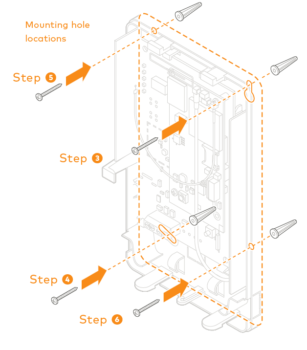
Place the SEM enclosure back plate against the wall at the desired mounting location and mark the four mounting holes.
Using the provided mounting screws and wall anchors (if needed), place the first mounting screw through the top-right enclosure hole. This screw will be used to hang the SEM from the wall while mounting and should not be tightened until the last step.
Place the second mounting screw through the bottom-left mounting hole. This screw is used to level the enclosure on the wall and should not be tightened until the last step. A standard leveling device may be used to ensure the unit is level.
Place the third mounting screw through the top-left enclosure hole. This screw should be tightened fully against the unit and wall before moving to the next step.
Place the final mounting screw through the bottom-right enclosure hole. This screw should be tightened fully against the unit and wall before moving to the next step. Note that this screw is critical for the wall tamper functionality and should not be overlooked.
Tighten the first two mounting screws fully to the unit and wall to complete the mounting process.
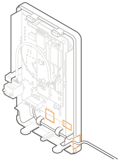
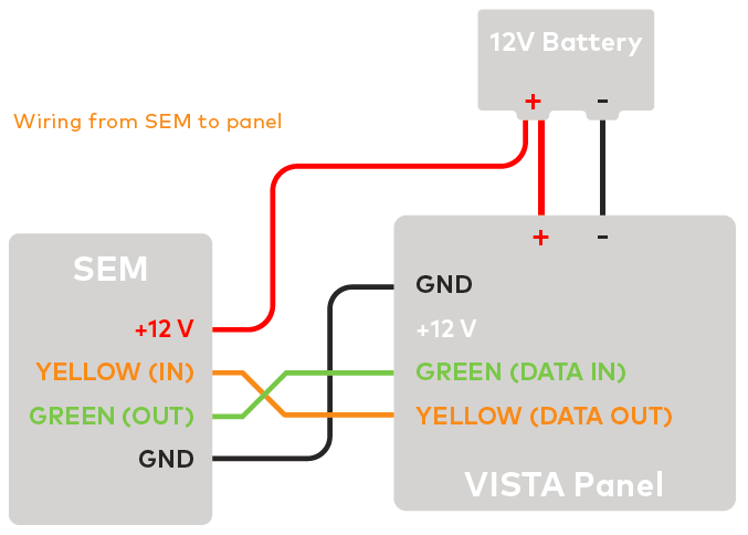
Connect panel terminal 4 (GND) to SEM GND, panel terminal 6 (GREEN: DATA IN FROM KEYPAD) to GREEN (OUT), and panel terminal 7 (YELLOW: KEYPAD DATA OUT) to YELLOW (IN).
Using the included red cable with the two-prong battery connector, connect the battery to both the SEM and the panel. For a power limited circuit, ensure the fuse is inside the Vista panel.
Connect an Ethernet cable to the pre-installed Ethernet jack to utilize Dual-Path communication. Local network changes may be required before the broadband path activates. For more information about Dual-Path communication,
Remove the snap-off plastics from the enclosure side at the desired locations, then route the cables around the internal strain relief walls and out the side of the enclosure.
Before completing the mounting, verify the wiring connections are secure and all internal components are in their proper location.
Then close the enclosure by sliding the cover into the mounting points at the top of the enclosure base and then swinging down the cover to snap the thumb tabs into place.
Reconnect the backup battery and restore AC power to the panel. On power-up, the SEM will enter programming to read the current installer code programmed at the panel, then perform a zone scan to read the existing zone information and settings programmed at the panel. During this process, the SEM will also automatically program-specific panel settings needed for the SEM to perform properly. The settings programmed are identified in Installation settings.
The zone scan will automatically begin after the panel is powered up. On the keypad you will see a series of disarms and programming setting changes before seeing MODEM COMM on the screen. If you have a non-alpha keypad, the keypad will show CC instead of MODEM COMM.
Do not touch the panel/keypad during this time
Zone scan (~5 minutes)
If you do not see the MODEM COMM message appear on the keypad during zone scan and instead notice the keypad scrolling through each zone individually, the SEM is using an alternate zone scan method because it is unable to access the downloader
When the zone scan is complete all user codes are synced to the Alarm.com Website.
Zone scan complete:

