IQ Pro Panel
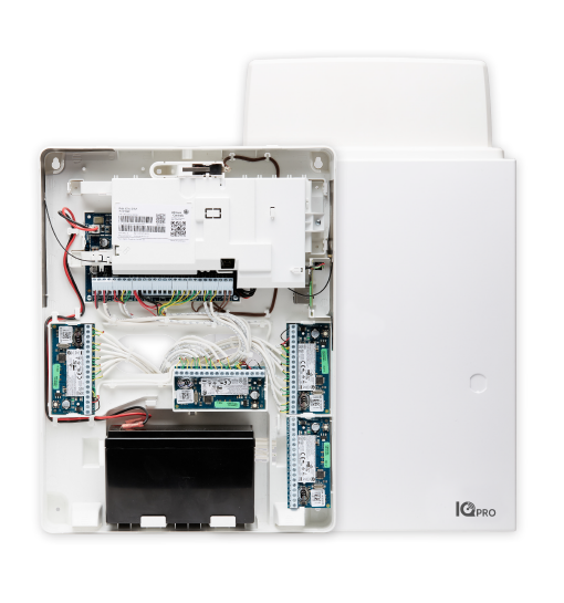
This how-to will cover the installation of an IQ Pro Panel on a new or existing panel and wiring of devices. Use the installation manual for reference found here.
Note: IQ Pro in plastic cover does not have the option for external antennas
Check out the Qolsys IQ Pro Best Practices for more information
Before you start:
- Put Monitoring account on Test Mode to avoid false dispatch
- Check to ensure all devices currently connected to the hardwired panel function before switching to the IQ Pro Panel.
Needed:
- Sharpie and tape to label wires
- Or any writing tool
- Precision Screw Driver
- Drill / Bits
- List of your zones
- Take a picture of your current panel incase you need to go back to it for reference
- Power Strip if needed (if using additional IQR-PG keypads).
Overview:
- Label/Remove Panel
- Install the IQ Pro Panel
- Connect Wires to panel
- Add Zone Expanders if needed
- Add Keypads if needed
Step 1: Label/Remove Panel
- Label all the wires to their proper zone number / Keypad location / Siren / Smoke Detector / Extras
- Unplug hardwired panel transformer from the wall and disconnect the wire as this will need to be replaced the transformer included with the IQ Hardwire PowerG.
- Disconnect the hardwired panel backup battery
The panel should now be powered down
- Remove all wires from the panel and zone expanders
- Remove the screws to remove the panel from the wall and take down panel
Step 2: Install IQ Panel pro
1.Before mounting panel, verify which keypad wires will need to go to power IQR-PG. Remove a knockout to have an exit route for these wires as these keypads require their own transformer. Sometimes a power strip is needed when using multiple IQR-PG.
2.Mounting the panel:
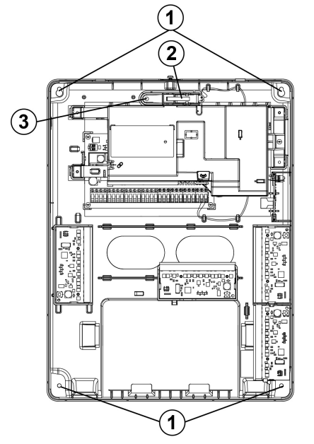
The panel will be a different size and will require new anchors and screws as seen in the diagram labeled as 1. Mark your spots, install the anchors, mount the anchors and then mount the panel.
3.Power up the panel:
Install the new 18VDC 2.22A power adaptor provided with the panel. Wire in the power to the panel and then add the transformer and plug it in. You can now add the 4Ah or a 7Ah
Step 3: Connect Wires to IQ Pro Panel
- 18V DC Terminals will go to your 18 V DC transformer provided.
- Bell terminals will either need a siren connected or a 1 kΩ resistor across the BELL+ and BELL- terminals or a bell trouble will appear on your panel.
- Corebus is where your keypad, zone expanders, and power supplies will be connected to.
- PGM outputs - PGM2 is used for 2-Wire smokes and 4-Wire smokes.
- Zones - Every two zones will share the center common
- For more Information on PGM outputs see here:
Qolsys/DSC Programmable (PGM) Outputs
Hardwired Smoke Detectors
-
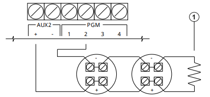
2 wire smokes:
- Wiring:
2 wire smokes is positive wire goes to Aux+ and Negative wire goes to PGM2 with a 2.2K Ohms end-of-line resistor - Programming: Configuration > Installation > Devices > PGM Outputs > PGM 2 > Tap the + icon and select 2 wire smoke > configure preferred settings and press save
- Wiring:
-
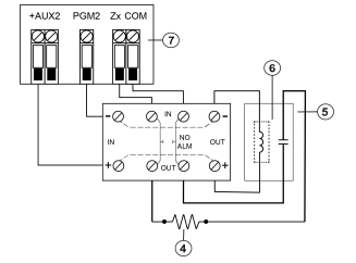
4 wire smokes:
- Wiring:
4 wire smokes will have the positive wire goes to Aux+ and Negative wire goes to PGM2. The green and yellow wires will go on the common and zone terminals. These will need a 5.6K Ohms end-of-line resistor
- Wiring:
Using MX Devices
MX are addressable sensors that can be ran using 18/2 wiring from one device to the next without having to have each wire home run to the panel. When using these sensor, you will need to use an HSM3105 zone expander. There are two power modes that can be used depending on the amount of MX devices being used.
-
Low Power Mode
When using Low Power Mode, you will wire in the HSM3105 directly to the corebus with a 22 Gauge 4 conductor wire not exceeding 3 ft. to the panel. The MX loop will have a maximum MX current draw of 67mA @ 40V (Equivalent to 360mA @11.3V or 325mA @ 12.5V). -
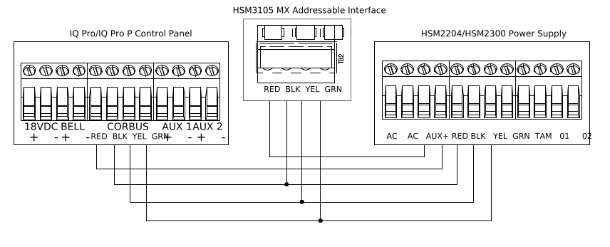
High Power Mode
Note: High power mode will need you to have an approved power supply being an HSM2300 or an HSM2204
When using High Power Mode, you will need an external enclosure like the HSC3010C to mount the Power Supply and the HSM3105 module. The HSM3105 will get power from either the HSM2300 or the HSM2204 and these can provide up to 228mA @ 40V (1000mA @ 12.5 V) or 260mA @40V (1000mA @ 11.3V)
Connecting to the IQ Pro Panel
- Open the IQ installer app, tap Start on the screen to begin.
- Tap Scan QR Code, then position your phone to scan the product information QR code inside the enclosure.
- Tap Continue.
- Press and hold the pairing tab on the PCB cover for one second, or until the green LED flashes red.
- When the LED flashes blue, tap Next on the screen.
- Enter the default installer code to connect.
- When prompted, change the default code to a new installer code.
- Select Dashboard at the bottom of the screen, then tap the Launch Wizard icon in the top right corner to initiate a step-by-step guide to configuring the IQ Pro system.
Assign Keypad Zones
- Installation > Devices > Security Sensors Select an enrolled keypad
- Select Edit > Keypad Input then select Enable or Disable
Enroll a Security Sensor
- Configure > Installation > Devices > Security Sensors
- Press the Add button
- Select Auto Enroll or Manual Enroll
- Auto Enroll: Start Auto Enroll > Open/Close or Tamper a sensor to enroll or hold the enroll button until LED flashes > Configure sensor and save
- Manual Enroll: Select sensor type > Enter Serial number > Configure sensor setting > Save
Delete a Sensor
- Configure > Installation > Devices > Security Sensors
- Scroll to sensor you want to delete and swipe to left
- Tap the delete icon to remove the sensor from the system