Installation overview and guidelines
Before beginning the module installation, get familiar with the following installation guidelines, the included manual, and the location of the module. The troubleshooting LEDs and their function are shown below and are referenced throughout this guide. Using these tips helps guarantee a successful module installation.
-
Turn off the Access Code Lock feature on the panel. This feature must be off for the system to communicate with Alarm.com. For more information, see here.
-
Installation consists of finding a mounting location for optimum wireless signal strength, mounting the module, wiring the module, and installing a case tamper (if necessary). Use the LTE Status LEDs on the module to check the signal strength before permanently mounting the module to avoid signaling issues after the installation is complete.
-
Power the module using the battery, not using the panel.
-
Perform a manual phone test (Comm Test) to initiate communication.
-
Observe panel power limitations as stipulated below:
- The module draws a maximum of 65 mA (continuous) in PowerSave Mode and 100 mA (continuous) in Idle Mode and Connected Mode from the panel. The module can draw up to 1600 mA (instantaneous peaks) from the panel.
- Do not exceed the panel total output power when using panel power for bus devices and hardwired sensors (refer to panel documentation).
- Use four-conductor, 22 or 18 gauge stranded wire to connect the module to the panel.
- 22 gauge = 40 feet (12.2 meters) Max Length
- 18 gauge = 90 feet (27.4 meters) Max Length
| Component | Function |
|---|---|
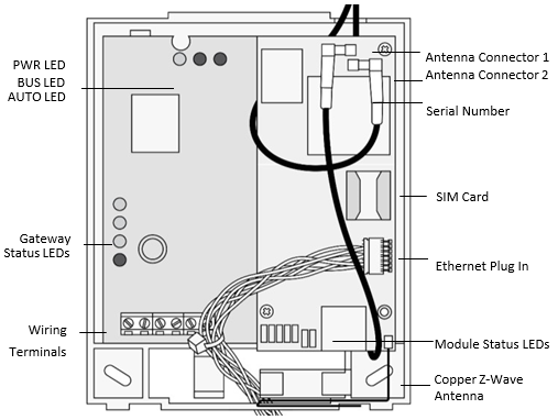
| PWR LED | Indicates module power status. |
| BUS LED | Indicates data bus activity between the panel and module |
| AUTO LED | Indicates module/data transceiver communication. |
| Gateway Status LEDs Indicates the current signal and status of the wireless gateway module. | Only the lower three LEDs are used. For more information, see Gateway status LEDs. |
| Wiring terminals | Provides wiring connection to the panel. |
| Antenna Connectors | Snap-in MMCX antenna connectors. The larger antenna connects to connector 1, the smaller antenna connects to connector 2. |
| Module status LEDs | Indicates communication with the LTE network, report errors, and signal strength. |
| Serial number | A 15-digit number found on the module. (Module Number) |
| SIM Card | Required for LTE communication. |
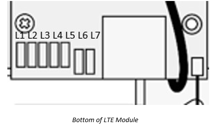
Module status LED functions
The following image is where L1-L5 status LEDs are found on the LTE module.
| LED | Function |
|---|---|
| L1 | General & Cellular Error LED L1 will flash one to eight times in a four-second interval to indicate specific error conditions such as a network error, panel communication error, or LTE radio error. For a list of the errors indicated by L1, see LED L1 (red). |
| L2 | Broadband & Panel communication LED L2 flashes every time the module communicates with the panel and flashes in patterns to indicate broadband troubles. |
| L3 | Call Radio LTE communication LED L3 flashes every time the cellular signal level is checked and when data packets are exchanged with Alarm.com and the LTE radio. |
| L4 | LTE signal level LED L4 flashes zero to five times indicating the module signal strength, or toggles on/off when communicating with the Alarm.com servers. |
| L5 | Z-Wave Error LED |
| L6 | Image Sensor. (model specific) |
| L7 | Image Sensor. (model specific) |
Module installation
Tools and supplies
The following tools and supplies are needed:
- Small blade and Phillips screwdriver
- Drill and bits for screws and/or anchors
- Wire cutter/stripper
- Four-conductor, 22-gauge or larger stranded wire
- #6 panhead screws (four included)
- Wall anchors (four included)
- 2 KΩ EOL resistor (included)
- Cat-5 Ethernet Cable (optional)
Module location guidelines
Prior to beginning installation, use the following guidelines to choose a location for the module:
- Do not mount the module gateway inside of the panel’s metal box. Doing so negatively impacts Z-Wave performance.
- Check the signal strength before choosing a location. Perform a walking signal strength test by powering the module using the battery directly (connect the GND and +12V terminals). After two minutes, LTE status LED L4 flashes between one and five times to indicate the LTE signal strength level (where five is the strongest signal). Alarm.com recommends a signal level of two or higher for proper operation of the LTE Module.
- Avoid mounting the module in areas with excessive metal or electrical wiring, such as furnace or utility rooms.
- Locate the module near an outside wall, preferably on an upper level.
- For homes or businesses located in canyons or with hills nearby, it is necessary to place the antenna higher in the building.
Mounting the module and connecting the antenna
Caution: Be free of static electricity before handling electronic components. Touch a grounded metal surface before touching the circuit board.
To mount the module:
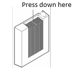
- Press down on the top of the enclosure cover as shown in the following image and set it aside.
- The LTE module requires two antennas for proper operation. Both antennas are pre-installed for convenience. The larger antenna is connected to antenna connector 1, and the smaller antenna is connected to antenna connector 2.
- The Ethernet port (optional) enables Dual-Path signaling to the Alarm.com cloud. If desired, the cable should be threaded through an opening in the gateway and plugged into the Ethernet connector on the module as shown in the antenna wiring orientation image.
- For optimal signal strength the antennas should be placed as far away from the module as possible and as far away from each other as possible. The recommended antenna orientation as shown in the following image.
The following image is the antenna wiring orientation.

- Place the module backplate on the wall at the desired mounting location, check for level, and mark the three mounting holes and the wire access area as shown in the preceding image. Leave room above the back plate to route the antennas.
- Set the back plate aside and drill holes at the mounting and wire access area locations.
- Use wall anchors where studs are not present and secure the back plate to the wall with the enclosed screws.
Wiring
To wire the module to the panel, do the following:
- Remove panel AC Power and disconnect the backup battery. This is necessary to prevent damaging the panel or module while making wiring connections.
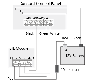
- Wire the module to the panel bus and to the battery terminals for power as shown in the following image.
Note : The module can also be powered off the SuperBus2000 two amp power supply (600-1019), but should not be powered directly off the panel.
The following image displays the wiring terminal.
- If required, connect an input device to the module Z1 and ZCOM terminals.
Power up
To power up the module and panel and start communication between them, do the following:
- Verify all wiring between the panel and module is correct.
- Connect the backup battery and restore AC power to the panel.
- Enter installer program mode and turn off the Access Code Lock feature if not already done. See here for more information.
- If you are already connected to ADC and just upgrading the module, this step is likely unnecessary, the feature should be off.
- Verify the LTE LED status does not display any errors.
- Verify LED L1 is not flashing any errors.
- Verify LED L4 is flashing an LTE signal level of two or higher. Otherwise, relocate the module.
- If LED L1 and LED L4 are not flashing, and LED L2 and LED L3 are flashing together, the module is in PowerSave Mode and the battery needs to be charged.
Perform an installer LTE manual phone test
** Note**: Before doing the manual phone test, the bottom red status LED should be on and the yellow status LED should be flashing.
To perform a phone test using the system keypad:
- Press [8].
- Enter the installer code (default 4321) or master code.
- Press [3]. The keypad should read Sensor Test 15 min Left.
- Press [1] or Off to disarm within 10 seconds of the last step.
- Enter the installer code or master code once more. This cancels the sensor test and sends a communication test to Alarm.com.
Surety Customers: If you already have an active Alarm.com account and you are updating your module (example, switching from 3G to 4G LTE) after module installation, but before running a cell test, you will need to login to your Surety account, access the System Manager feature, and enter your new 4G LTE module’s 15-digit IMEI number to associate the new module with your Alarm.com account.