Pre Connection Checklist
The Installer Code
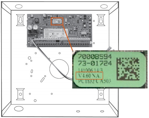
The SEM is a bit different when it comes to Alarm.com compatibility. It requires that the user have access to their panel’s Installer Code prior to the creation of their Alarm.com account. This code is necessary as Alarm.com uses this code to access panel programming and read information stored on the panel.
Tools and supplies needed
- Small blade screwdriver and Phillips screwdriver
- Drill and bits for screws and/or wall anchors
- Alpha keypad
- Alarm.com strongly recommends installing an alpha keypad with at least 32 zones to ensure the “Communication Failure” trouble condition is displayed to the user.
- Four-conductor, 22-gauge or larger stranded wire
Installation Guide
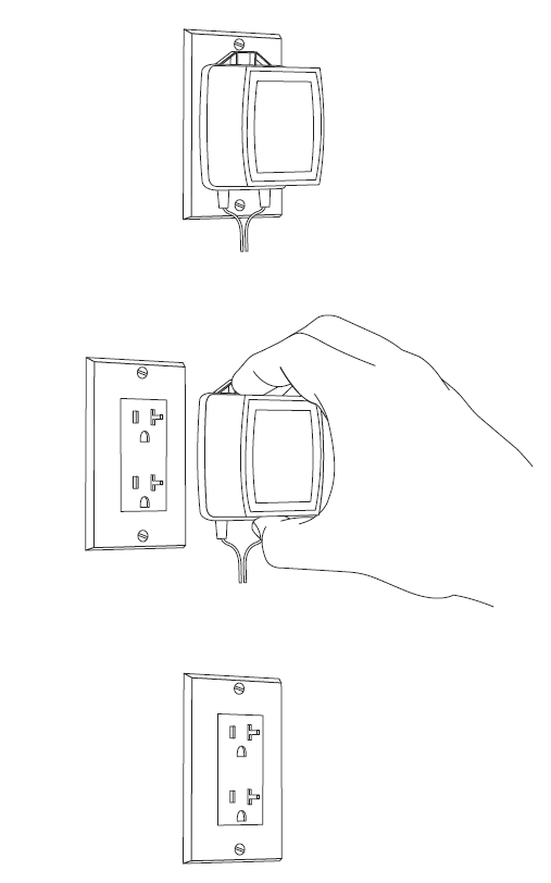
Disconnect power from the panel
Prior to disconnecting power from the panel, first verify that the panel is disarmed.
Next, remove panel AC power and disconnect the backup battery.
Caution : This is necessary to prevent damaging the panel or module while making wiring connections.
Mount the SEM
Caution : You must be free of static electricity before handling electronic components. Touch a grounded metal surface before touching
the circuit board.
- Press down on the bottom tabs of the enclosure cover to remove it and set it aside.
- Carefully remove the SEM circuit board by depressing the interior bottom tab.
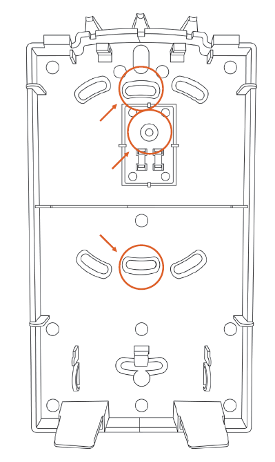
- Place the SEM back plate on the wall at the desired mounting location and mark the three mounting holes as shown below.
4 Set the back plate aside and drill holes at the mounting locations.
- Use wall anchors where studs are not present and secure the back plate to the wall with the enclosed screws.
- Insert the SEM circuit board back into the back plate.
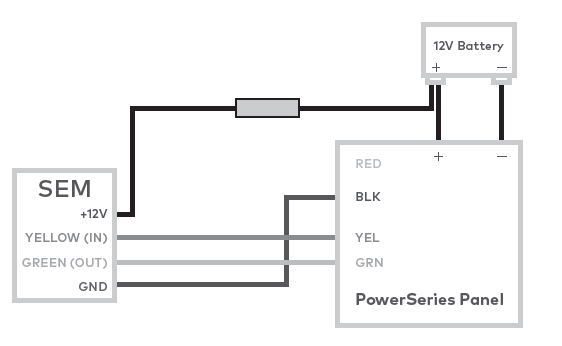
Wire the SEM to the panel
Caution : Verify panel AC power is removed and the backup battery is disconnected.
- Connect panel terminal SEM GND to BLK.
- Connect panel terminal YELLOW (IN) to YEL.
- Connect panel terminal GREEN (OUT) to GRN.
- Use the included red cable with the two prong battery connector to connect the battery to both the SEM and the panel. For a power limited circuit, ensure the fuse is inside the PowerSeries panel.
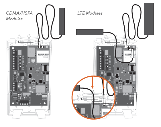
Once wiring is complete, route the antennas outside of the enclosure, away from the SEM, and replace the enclosure cover.
Note : The antennas should be routed through the second and third channel openings at the top of the enclosure as shown in the following images:
Dual-Path (Optional)
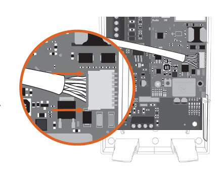
For Broadband Ethernet, connect the provided Ethernet Dongle to the connector on the SEM.
Connect the Ethernet cable to the provided Ethernet Dongle.
Power up the panel
Connect the backup battery and restore AC power to the panel. For the SEM to interact with the existing zones on the system, it must read them from the PowerSeries panel. The SEM does a zone scan to read this information.
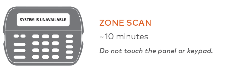
The zone scan automatically begins within one minute after the panel is powered up and should take between 5 and 15 minutes, depending on the number of partitions and zones on the system. Do not touch the panel, keypad, or SEM at this time.
The zone scan is complete when the green and yellow lights on the keypad remain solid. If you press any buttons on the keypad during the zone scan, the message System unavailable displays on the screen. The date and time shows on the screen when the zone scan is complete.
Important : If the system was previously communicating over a phone line, we recommend Disabling Telco Line Monitoring (Section 015, Option 7) and Removing the Phone Numbers (Section 301-303).
Broadcast sensor names
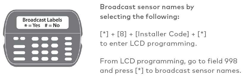
For the SEM to be able to read the sensor names stored on the panel and display them on Alarm.com, you must broadcast the sensor names stored on the keypads. This should be done for every install with an LCD keypad and is necessary even if there is only one keypad on the system.
Default Installer Code:
5555
Add & delete Z-Wave devices
Alarm.com does not recognize any Z-Wave devices previously learned into the panel. These devices need to be deleted from the previous Z-Wave network and added to the SEM to use Alarm.com’s home automation services (e.g. automation control via website, app, and intelligent automation rules).
Adding Z-Wave devices
- Press and hold Z-Wave button on the Alarm.com module.
- Release the button once LED L5 flashes in groups of four. L2 also flashes.
- Trigger a device to add it to the network.
- When a device is added successfully, L5 illuminates solid.
- You need to re-enter Add Mode before triggering the next device.
Note : If you can’t add a device to the network, you may need to delete the device’s current network data using the device deletion process before you can add it to the new network (some devices come from the factory with network data)
Deleting Z-Wave devices
- Press and hold the Z-Wave button on the Alarm.com module.
- Release the button once LED L5 flashes in groups of two. L2 also flashes.
- Press and hold the Z-Wave button on the module a second time.
- Release the Z-Wave button once LED L5 flashes in groups of two.
- Trigger a device to erase its network data and delete it from the network.
- When a device is deleted successfully, L5 illuminates solid.
- You need to re-enter Delete Mode before triggering the next device.