Could the wiring here be used to power a IQ2+ panel, and if so could you describe how.
Thanks
How many keypads do u have on the system currently
I can’t precisely tell by that image. We would need to know the gauge of the wiring, and just as important, the length of the cable back to where the power supply would be.
Back in the wall behind the back-plate you should be able to view the cabling sheath, which will have the gauge written on it “XX AWG” typically.
I would guess 22 AWG, but I cannot say for sure.
How far is it between that keypad and the primary control panel? Estimate a little extra for the path the cable must take through the walls.
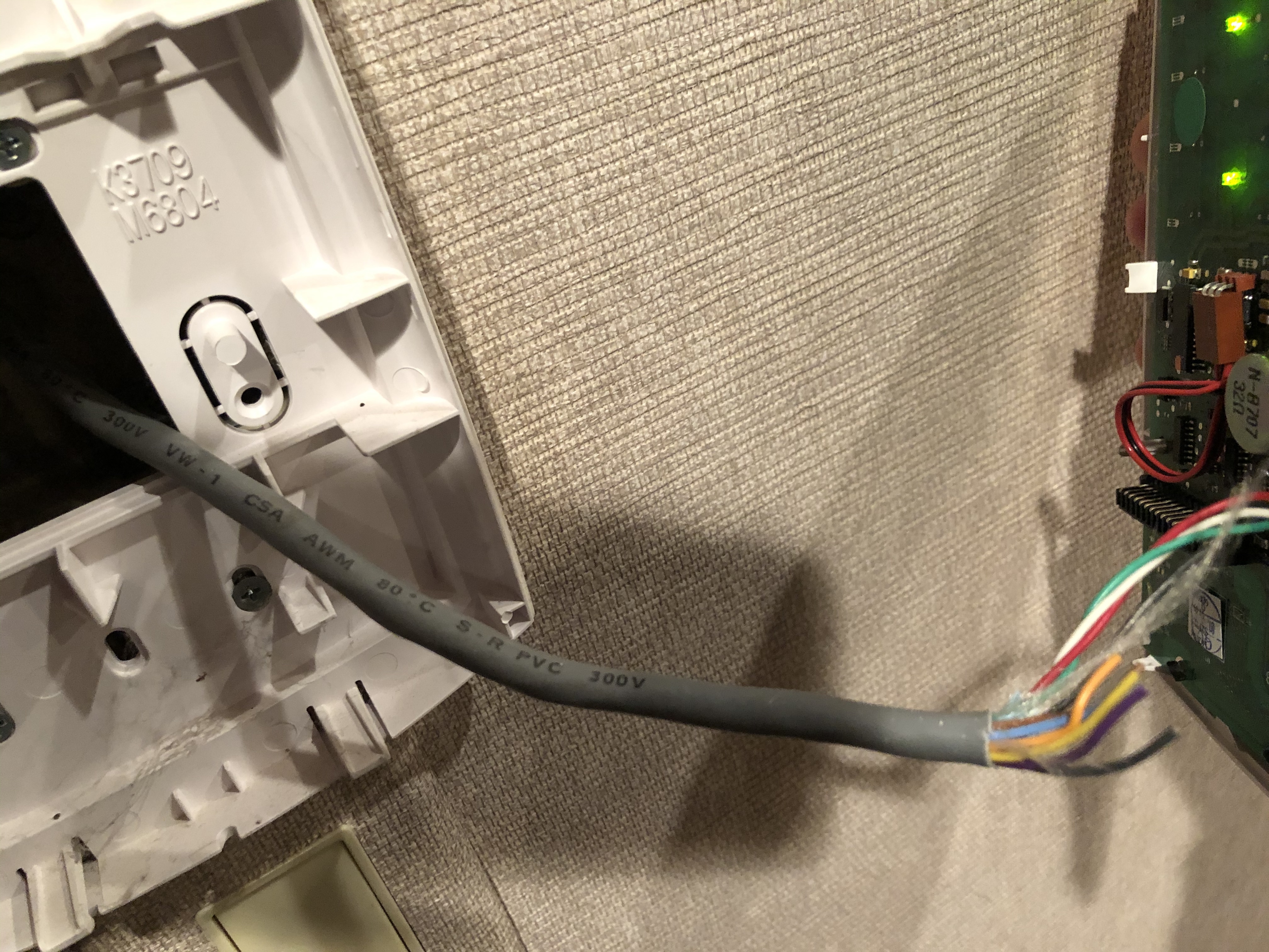
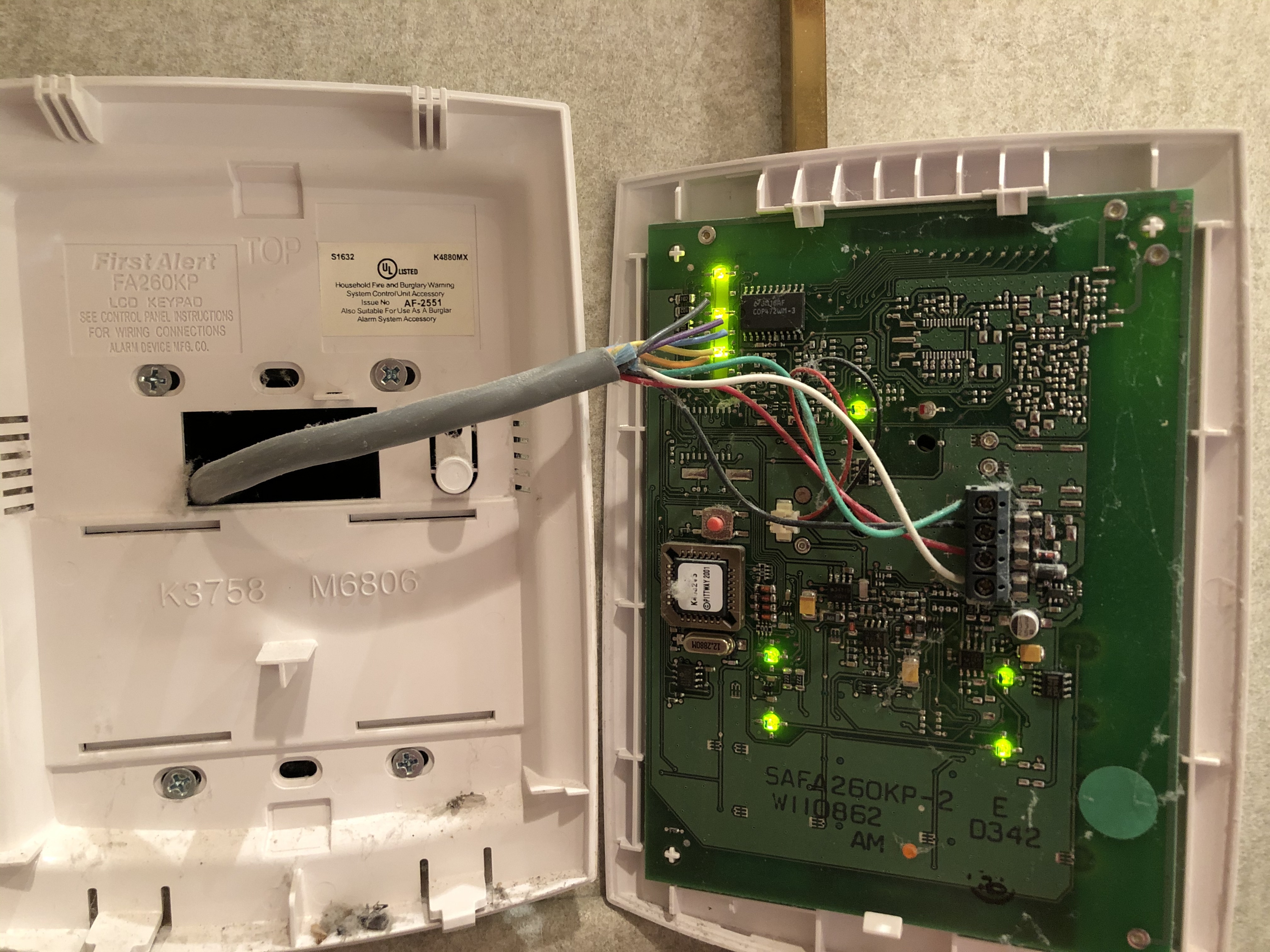
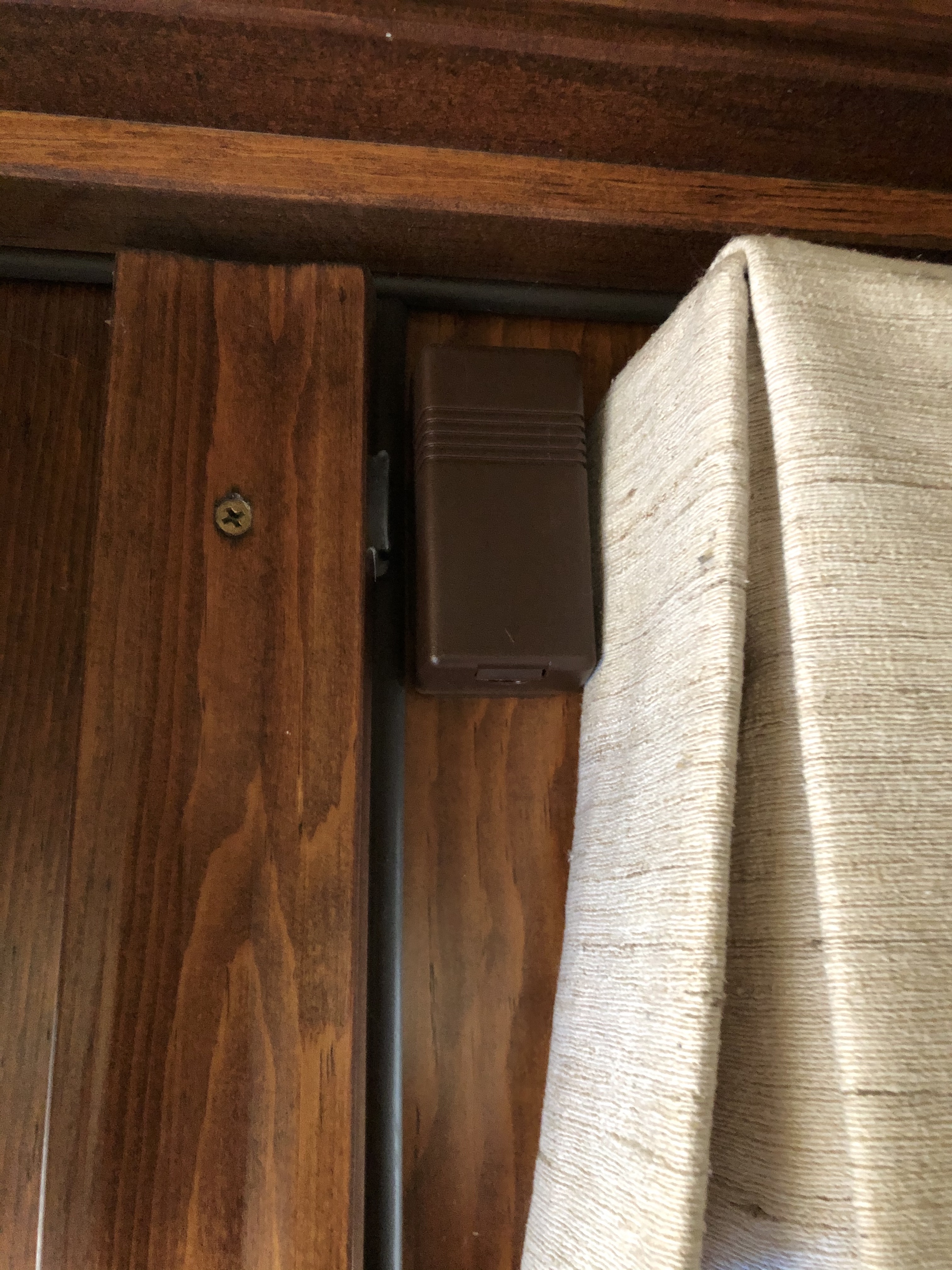
Here is where one panel is located, about 33 ft from the can. The sheath doesn’t appear to specify the gauge?
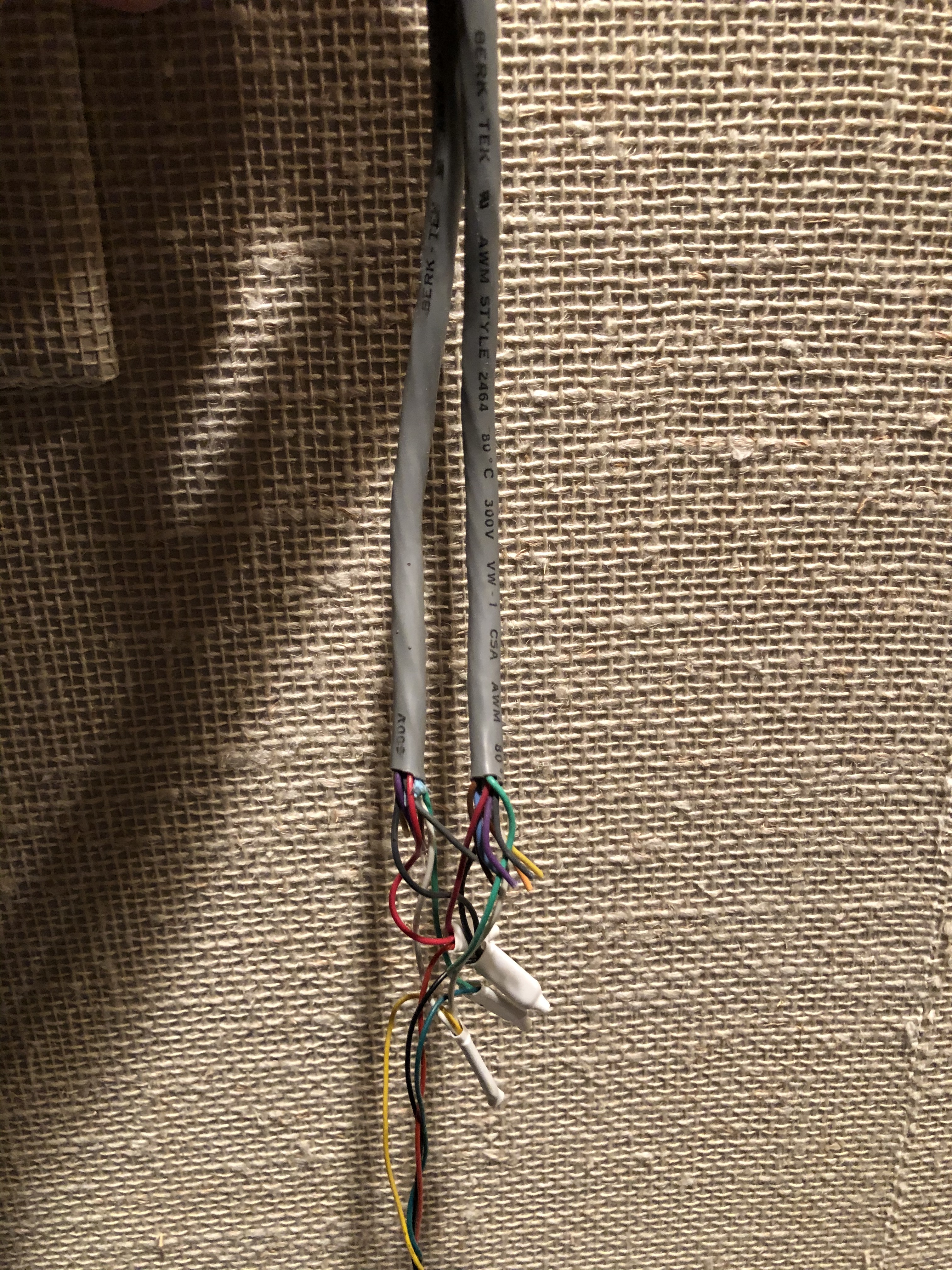
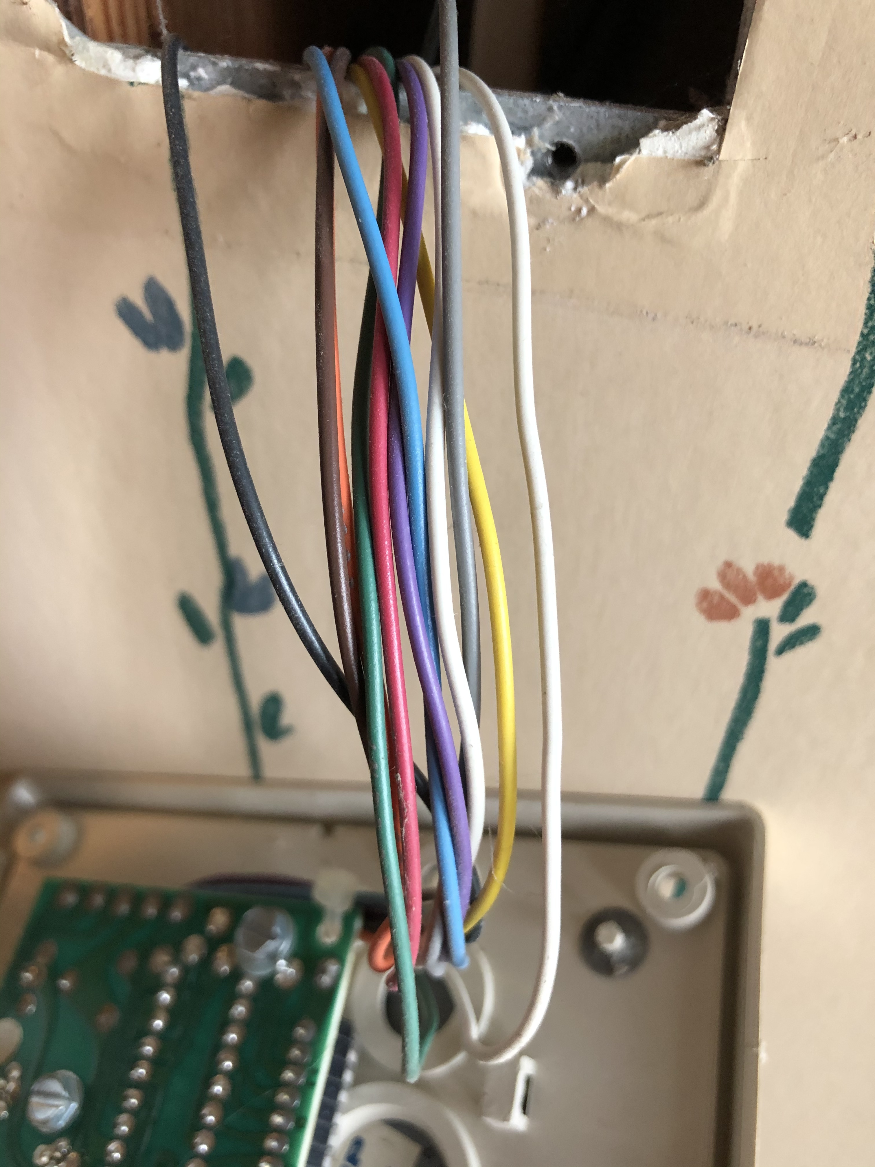
And here is the wiring at a second panel, located about 37 ft from the can. It appears to have two of the sheaths at the first can wired in series to the panel.
What are the four wires going to the panel (green/white/red/black at the first panel, and yellow/black/red/green at the second panel), and what are the wires with cut ends?
Are you able to tell if I could use the existing wiring to power an iq2+ at one or both locations?
Thanks
So you just have the two keypads?
Based on that second image it looks like what the original installer did was instead of running a dedicated cable to each keypad location, they ran one cable that goes from the panel to one keypad to the next keypad.
The second image (the location you call the second keypad) is actually the first one in the wiring sequence. That is where the wire from the panel first goes. They have cut the feed cable and spliced on four wires for that keypad.
The wire then travels directly from the one in your second image to the keypad in your first image.
Ultimately, you should be able to wire up and reuse the wiring at the location in your second image. There are enough conductors there that you shouldn’t have to worry about voltage drop. You could use four conductors for each terminal. You would just need to figure out which of the two cables where it is cut and spliced is coming from the panel and which is going to the next keypad.
I don’t know about the location in the first image. It would have 37 feet plus the additional distance between it and the other keypad to contend with, and you would need to splice the wires all back together for one long continuous run. It may be possible, but it is really hard to say how much extra distance is on the cable there.
There are actually four keypads - does that make a difference?
Yes, it does.
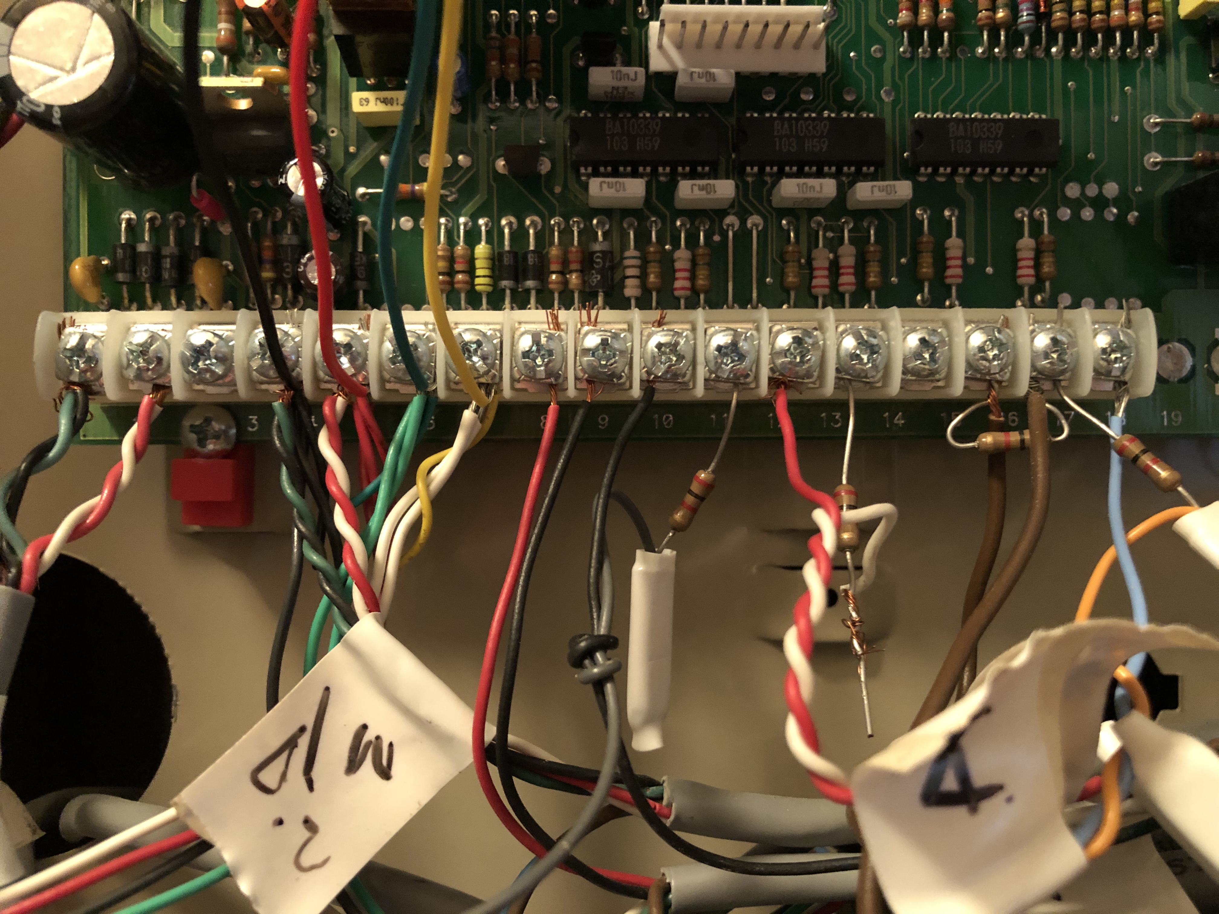
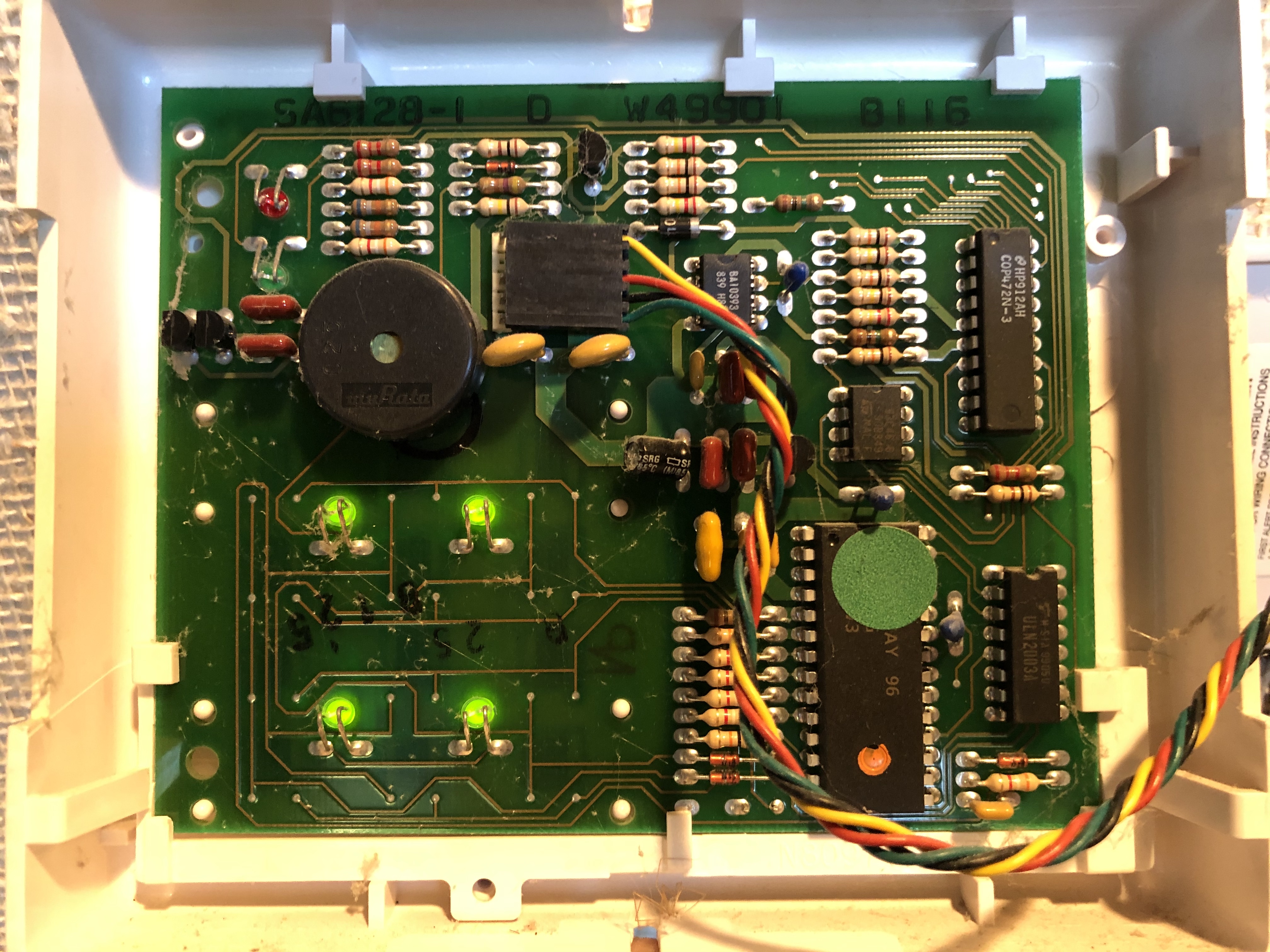
How many wires are connected to the keypad inputs at the panel? Can you post a photo of the panel board (in the can)?
It is possible they may have used a single cable bundle for all 4 keypads. Unfortunately if that is the case you would need to test to determine the wiring order, which one is first second and third.
There is a photo of the can at the top of the thread.
How would I determine the wiring order?
Specifically, we would need a clear image of what is attached to the keypad inputs on the board. It is difficult to tell in that image what is connected.
It does appear that there are two wires connected to terminals 6 and 7, the data terminals.
Do those two wires on each go to different cable bundles? Are those bundles labeled?
Can you provide a photo of what is behind the other two keypads in terms of wiring?
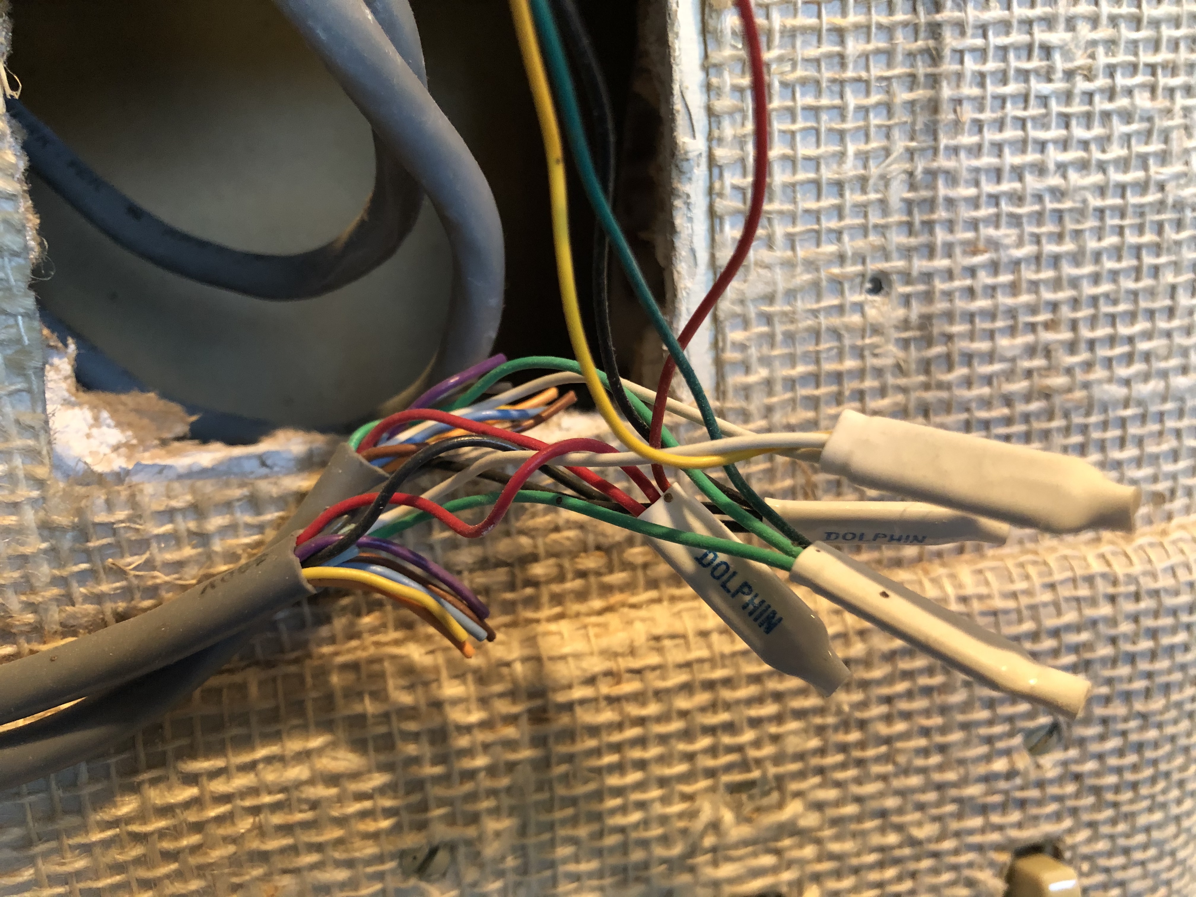
Each of the two green wires on terminal 6 does come from a different bundle, and each bundle is labeled as coming from two different areas of the house.
Each of the two white wires on terminal 7 comes from the same two bundles as the green wires, one from each bundle.
Each of those two bundles also has red and black wires going to terminals 5 and 4, respectively.
In addition to these two bundles, there are four others - one similarly sized to the above two, and three smaller ones, with wires going to other various terminals.
Note that last keypad is currently non-functional, as it was not updated at the time the other three were.
If the 4th is not currently connected, that helps explain what you have.
Looks like you just have the first two keypads using the one cable bundle. The third keypad appears to just be directly wired back to the can (the second wire bundle connected to the keypad inputs)
This post should still be correct.
I can’t speak to the fourth set of wires if they are not connected. You’d need to determine where the other end of those wires is. They would not be connected at the panel.
numbering the keypads in the order the photos are posted, my goal is to place keypads at the first and second locations.
is it possible the second keypad is spliced to provide a feed to the third (rather than to the first) keypad? i ask because that would seem to make more sense based on the locations of the pads in relation to the panel. if that were the case, then can you tell from the photos whether the first keypad is wired directly to the panel? does this matter? if it does matter, how could i confirm this?
could you explain in more detail how to do this, ie install and power an IQ 2+ panel with the existing wiring? below are additional photos of what i’ve called the second panel.
is it possible the second keypad is spliced to provide a feed to the third (rather than to the first) keypad? i ask because that would seem to make more sense based on the locations of the pads in relation to the panel. if that were the case, then can you tell from the photos whether the first keypad is wired directly to the panel? does this matter? if it does matter, how could i confirm this?
It looks like the same basic colors are being used, so yes, that is actually possible. I cannot tell definitively by looking at the photos. If the keypad wires are not labeled in any way, to definitively know which wires match up to which locations, you would need to test.
This can be done one of a couple ways. One way is using a multimeter to test continuity. Do you have a multimeter/ohmmeter?
If everything is currently powered and working, an even easier way that requires no testing equipment is to power off the system, remove one of the bundles of keypad wires that have four wires going into terminals 4-7, then power up the system and see which keypad(s) power up.
You should either see two or one keypad not working, which will tell you which keypads are wired together and which wires go to each. (Whether the first or third keypad is connected to the second one.)
could you explain in more detail how to do this, ie install and power an IQ 2+ panel with the existing wiring? below are additional photos of what i’ve called the second panel
Certainly. Choose two colors of wire to connect to + and two colors to connect to -. Connect the two you chose for + to the 5vDC to 7vDC IN terminal on the panel. On the other end, connect those two wires to the + terminal on the included plug-in power supply that comes with the IQ Panel 2+. Connect the two wires you chose for - to GND on the panel terminal block. Connect those to - terminal on the power supply.
Once you know which keypads are wired together I can provide a more specific instruction for those locations. Let me know where you want to put the new panel and which existing keypads are sharing the cable.
finally getting back to this project
how could you tell this? is that a 345 mhz receiver mounted above the main panel? is it relaying the information from the wireless sensors to the main panel, since the landline is connected to the main panel?
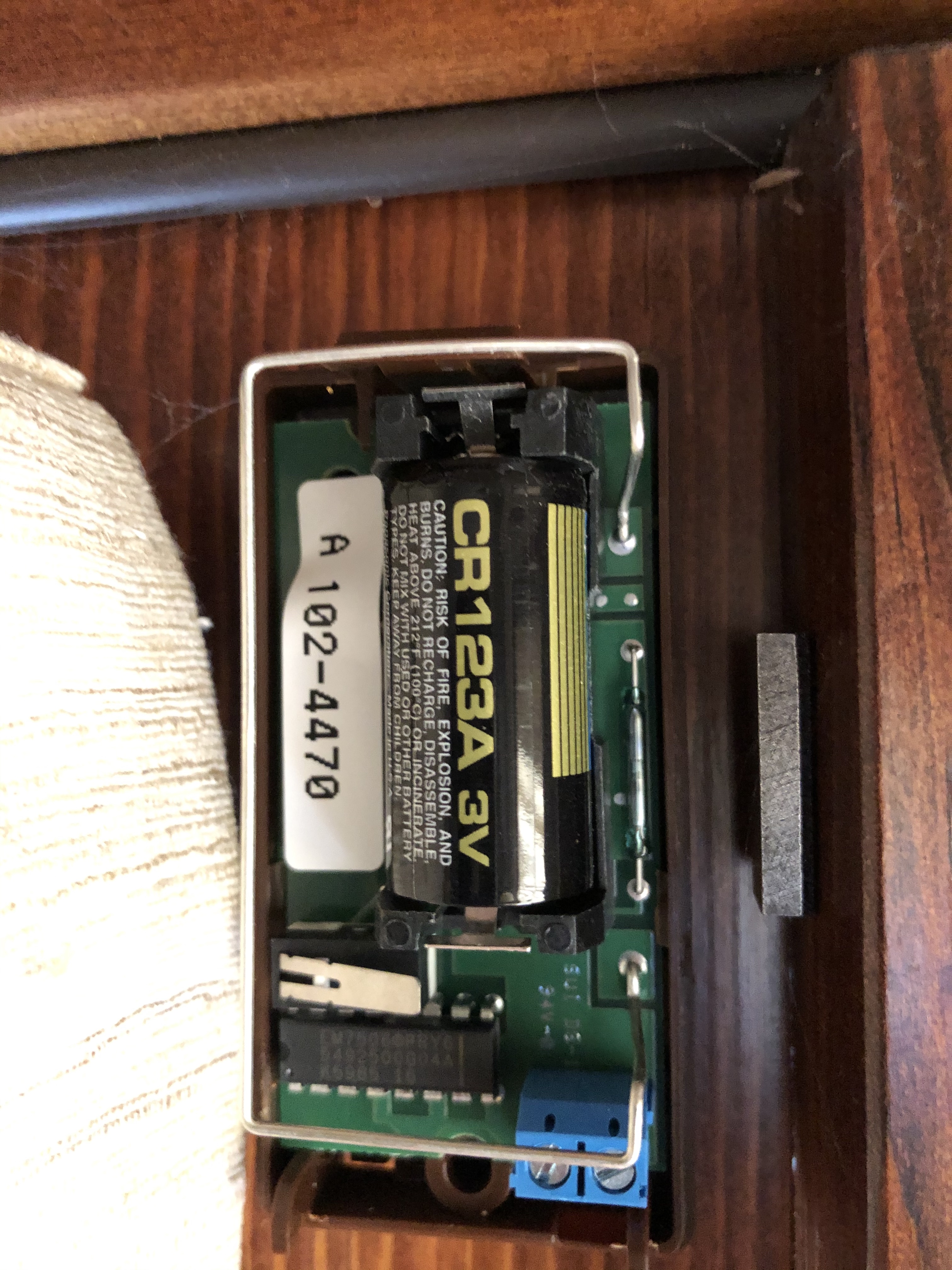
these are the wireless D/W sensors. are you able to tell the make and model?
it turns out there are more of them than i had originally known, so i may want to continue using them - i would be able to enroll them with the 345 mhz IQ2+ panel, right?
just to confirm - to replace the current setup with a power G translator for use with an IQ2+, i would remove the entire current can from the wall and mount the power G translator in its place. terminals 8-17 would transfer over to six zones of the power G translator. zones 5 and 6 are IR (I believe) beams that function like tripwires - i assume these are powered off the aux power terminals 4 and 5 and would be transferred to the aux power terminals of the power G translator? nothing currently wired to terminals 6 and 7 or 21-25 would be used in the new system? would the smoke detectors in zone 1 (terminal 8 and 9) simply transfer over to any one of the power G translator zones?
would it be possible to use some of the existing wiring to power the IQ2+ panel at the location of one of the existing keypads via the auxiliary power terminals of the power G translator?
how could you tell this? is that a 345 mhz receiver mounted above the main panel?
If you have a Honeywell panel installed, it is likely that any wireless sensors paired with it operate on the 345MHz frequency, which is what all Honeywell brand 5800 series wireless sensors communicate on.
Based on the picture, that brown sensor appears to be a Honeywell brand 5816WMBR door window contact which communicates on the 345Mhz frequency.
it turns out there are more of them than i had originally known, so i may want to continue using them - i would be able to enroll them with the 345 mhz IQ2+ panel, right?
So long as you have the Qolsys IQ Panel 2+ (2GIG & Honeywell 345MHz) QS9201-5208-840. This version of the Qolsys panel has a 345Mhz radio and a DSC PowerG radio installed. It would not work with Qolsys/GE 319.5MHz sensors nor would it work with newer 2GIG eSeries 345MHz sensors.
Newer Qolsys panel purchases should have the 7vDC transformer.
just to confirm - to replace the current setup with a power G translator for use with an IQ2+, i would remove the entire current can from the wall and mount the power G translator in its place.
If that works best for your layout, you can, but you can leave the old panel in place as well since your just transferring existing wiring to the PowerG PG9WLSHW8
… i assume these are powered off the aux power terminals 4 and 5 and would be transferred to the aux power terminals of the power G translator?
From the manual
Aux 1 terminal is used for powering intrusion sensors, like Motion detectors.
Aux 2 terminal powers life safety devices (Smoke, Heat, CO)
would it be possible to use some of the existing wiring to power the IQ2+ panel at the location of one of the existing keypads via the auxiliary power terminals of the power G translator?
The Qolsys IQ Panel 2 would need to be powered off of its own included transformer. Should the included cabling be insufficient, you can use the following:
5.5vDC Transformer: Use 18AWG wire
no longer than 25ft to ensure sufficient
power is received at the panel.
7vDC Transformer: Use 18AWG wire no
longer than 100ft to ensure sufficient
power is received at the panel.
how is the 5816WMBR enrolled into the IQ2+? I can’t seem to find an installation manual. any reason I wouldn’t want to continue using these sensors, or are they typically reliable?
Its learned in like any Door Window contact through Auto Learn Putting a 345MHz compatible IQP2+ into Auto Learn mode then tripping the sensor should automatically populate values. Loop 2 would be selected for the internal reed switch (magnet).
5800 series Honeywell wireless sensors are reliable and have been in use for many years. The only real reason to replace them would be if they aren’t functioning or if you are looking to upgrade to an encrypted sensor, like PowerG.
zone 1 (see photo in post #30) is wired. however, the system currently has honeywell 5808W3s. i assume these aren’t related? what could the wiring in zone 1 be for? i’m not aware of any other smoke detectors in the current system…
would i be able to use the 5808W3s with the 345mhz IQ2+?
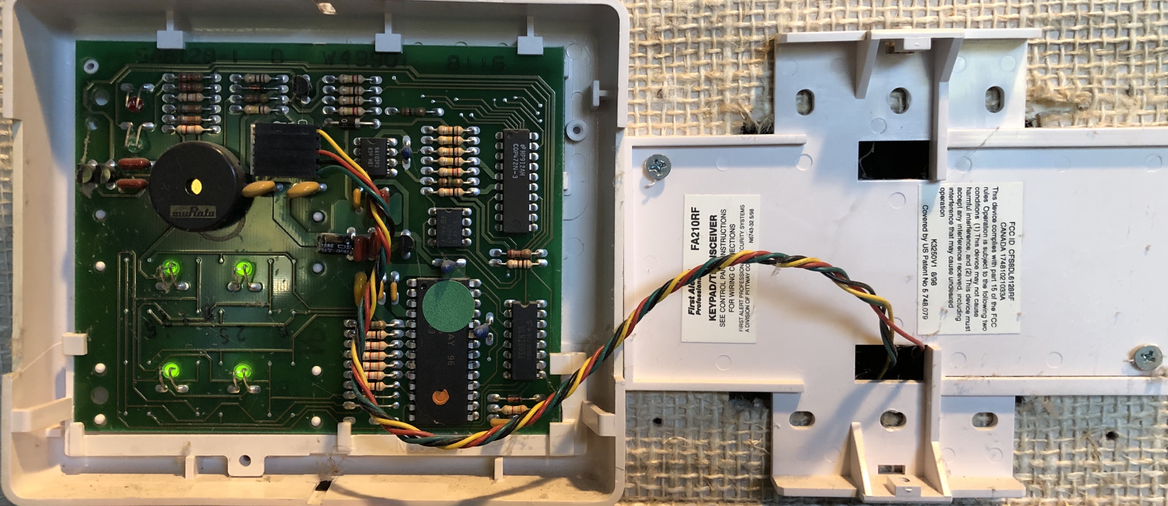
does the First Alert 148 comprise both panels in the photo in post #4, or just the larger of the two? if the latter, what is the model of the smaller of the two panels which appears to be the receiver for the wireless sensors?
zone 1 (see photo in post #30) is wired. however, the system currently has honeywell 5808W3s. i assume these aren’t related? what could the wiring in zone 1 be for? i’m not aware of any other smoke detectors in the current system…
Is that a zone currently learned into a Surety account or is this a separate system?
I wouldn’t be able to say for sure what a wire would be connected to locally. You’ll need to check for labeling/sensor zone list written on documentation, or test zones.
I can tell you the resistor is not wired properly for a smoke detector, so it is likely not a smoke circuit.
No, wireless detectors would be unrelated to a wired zone.
would i be able to use the 5808W3s with the 345mhz IQ2+?
Yes, that model is compatible. You can view a compatible sensors list here (see the 345 section.)
does the First Alert 148 comprise both panels in the photo in post #4, or just the larger of the two? if the latter, what is the model of the smaller of the two panels which appears to be the receiver for the wireless sensors?
The main panel is the lower, larger board.
The upper smaller one is a 5881 wireless receiver.
It’s currently on a different system that I’m converting to surety. The written paperwork says it’s a fire zone. The only smoke detectors I see are the wireless ones I mentioned. The house also has a sprinkler system - could it be related to that? How would I best test this zone? Trying to figure out what to do with it when moving these zones to a HW16 or power G translator.