Alarm.com Smart Thermostat HD ADC-T40K-HD - Installation Guide

Installation precautions

  • Before installing the Smart Thermostat HD or servicing the HVAC equipment, turn off power to the system.
  • Leave power off until you have finished installing or servicing the HVAC equipment.
  • Shorting the electric terminals at the control on the heating or cooling system is not recommended. Do not test the system this way.
  • When testing the existing system or the new Smart Thermostat HD do not run the cooling system when it is cold outside as this may harm the compressor. Please wait for mild temperatures before testing the cooling system.
  • You must follow all local codes and ordinances for wiring the system.
  • The Smart Thermostat HD should only be powered by a listed Class 2 power supply at 24 VAC (C-wire or wall transformer).
  • A current higher than 1 amp to each thermostat terminal may cause damage to the thermostat.
  • Verify that the system is 24 VAC. If the old system is labeled as 120 V or 240 V or has wire nuts, the system is high voltage. Do NOT install this thermostat on a high voltage system. Contact a local HVAC professional for help.

In the box

In_the_box

  1. Trim plate
  2. Thermostat
  3. Display
  4. Drywall anchors x2
  5. Wall screws x2

Recommended tools

Recommended_tools

  1. Phillips screwdriver
  2. Pencil to mark mounting location
  3. Power drill – 3/16" (#13) drill bit
  4. Needle nose pliers
  5. Camera

Overview

Thermostat

  1. Status LED
  2. Reset Button

Display

  1. Settings menu
  2. Current setpoint
    • Note: To change the setpoint, tap on the up or down arrow.
  3. Indoor temperature
  4. Current mode
    • Note: To change the mode, tap on the current mode icon.

Location

  • If replacing an existing thermostat, the new Smart Thermostat HD can be mounted in its place. If a new location is desired it will be necessary to move the wiring.
  • New installations and relocations should follow the accompanying guidelines to Verify the most accurate temperature reading and ease of use.
  • Mount on an inside wall, approximately 5 ft. (1.5 m) above the floor in a frequently used room.
  • Do not install in locations near appliances or devices that affect the local temperature such as televisions, lamps, or dryers.
  • Avoid areas that are exposed to large temperature variances, such as: direct sunlight, near an AC unit, above or below auxiliary heat and air vents, and drafts from windows or exterior doors.
  • Be aware of what is on the other side of the wall where the installation is occurring. Do not install on walls adjacent to unheated rooms, stoves, or housing hot water pipes. Exterior walls are also not ideal locations for installation.
  • Damp areas will not only affect the humidity reading but could lead to corrosion and shorten the lifespan of the thermostat.
  • Install in a location with good air circulation. Stagnant air will not accurately reflect the rate of temperature change in the room.
  • Avoid areas behind open doors, corners, and alcoves.
  • Wait until construction and painting are finished before installing.

Preparation

  1. If you will add the Smart Thermostat HD to a Z-Wave network, power on the controller and verify it is communicating.
    • Note*: If the Z-Wave network supports SmartStart, use the MobileTech app to scan the QR code found on the Thermostat or the box.
  2. Test the existing system.
    • Verify that the heating and/or cooling system is operating properly before you try to install the new Smart Thermostat HD.
    • Caution: Do not test the system by shorting electric terminals. Do not test the cooling system if it is cold outside, as this may harm the compressor.
  3. Turn off power to the HVAC unit.
    • Turn all heating and cooling systems off. This can be done at the circuit breaker.
    • Caution: Do not remove the existing thermostat until power has been turned off at the circuit breaker.
  4. Remove the existing thermostat.
    • Remove the cover from the existing thermostat. Do not disconnect the wires yet.
    • Verify the wires are identified correctly. If you have an unidentified wire, it may be necessary to identify where the wire connects to the heating or air conditioning equipment.
    • Caution: Wiring can vary for each manufacturer. Identify all wiring designations before removing it from the existing thermostat.
    • Take a picture of the wires before you detach them from the existing thermostat for future reference.
    • After all wires are identified and a picture has been taken, disconnect all the wires and remove the existing thermostat. Remember to secure the wires so they do not fall into the wall.
  5. Prep wires (if needed).
    • Verify the wires are a proper gauge between 16-24 AWG (1.3 – 0.5 mm).
    • Verify wires have exposed straight ends of the appropriate length.

Thermostat installation

  1. Level and mount the Thermostat to the wall with the supplied hardware.
    • If additional support is necessary, drill holes with a 3/16’’ (#13) drill bit and tap in the drywall anchors.
    • If you need to cover up any marks or holes from the previous thermostat, mount the trim plate prior to securing the Thermostat to the wall.
  2. Insert the wires into their designated wire terminals. See the table for details.
    Insert_wires_into_designated_wire_terminals

Important: If you only have one R wire, insert it into RH. Only connect wires to the thermostat that will be used by the system. Inserting wires that are not connected to or used by the HVAC system could cause the Smart Thermostat HD to operate improperly.

Caution: Do not insert more than one wire into a wire terminal as this will damage the wire terminal. If you only have one R wire, there is no need to physically jump RH and RC. The Thermostat will internally jump the two terminals.

Terminal Description
RC Cooling power
RH* Heating power
W2 Heat/aux stage 2
W Heat/aux stage 1
C* Common wire from transformer
Z1 Configurable: W3, humidifier, dehumidifier, vent
Z2 Configurable: W3, humidifier, dehumidifier, vent
Y Cool/pump stage 1
Y2 Cool/pump stage 2
G Fan
O Heat pump reversing valve (Energized in COOL mode)
B Heat pump reversing valve (Energized in HEAT mode)

*Note : Required wire.

  1. After all wires are inserted into the wire terminals, restore power to the HVAC system.

    • This will supply 24 VAC power to the Thermostat.
      Restore_power_to_the_HVAC_system
  2. Check the Status LED, which will indicate the Thermostat has power.

    • If the Status LED is off, it indicates the Thermostat does not have 24 VAC power.
    • Visually verify both RH and C are securely inserted into the appropriately labeled terminals.
    • Verify the HVAC system has power, this may be identified at the unit.
    • Verify the circuit breaker was correctly turned back on.

Display installation

  1. Connect the Display to the Thermostat. Magnets will hold the Display in place.
    Connect_display_to_the_thermostat

  2. The Display will turn on after being connected.

    • Note : If the Display does not power on after 30 seconds, verify 24 VAC power is being supplied to the Thermostat from the HVAC system.

Add the thermostat to the Z-Wave network

Test the system

Caution: Do not test the cool mode during cold weather. Wait for mild weather to fully test the system.

  1. After successfully installing and setting up your new Smart Thermostat HD, please test the Smart Thermostat HD and HVAC system.
  2. If the Smart Thermostat HD will control a heating system, test the heating system by changing the mode to HEAT and adjusting the setpoint to be higher than the current room temperature. Verify the heating system turns on and that the room is starting to warm up.
  3. If the Smart Thermostat HD will control a cooling system, test the cooling system by changing the mode to COOL and adjusting the setpoint to be lower than the current room temperature. Verify the cooling system turns on and that the room is starting to cool down.

Additional Information

Factory reset the Smart Thermostat HD

The Smart Thermostat HD can be reset to its factory settings. This will reset all HVAC settings, rules, and schedules. It will also delete the Smart Thermostat HD from the Z-Wave network.

To reset using the Display:

  1. Tap MENU) on the display.
  2. Tap Installer Settings.
  3. In Installer Settings, tap OK.
  4. Tap Reset to Default.
  5. In Confirm Action, tap OK.
  6. The display will cycle through and show a confirmation message when the reset is complete.

To reset without using the Display:

If you are unable to use the Display, you may also reset the device to factory settings from the Thermostat.

Note: It is recommended to delete the Smart Thermostat HD from the Z-Wave network before performing this reset.

  1. Remove the Display.
  2. Press and hold the reset button on the back of the Thermostat Display for 30 seconds.
  3. When the Status LED slowly blinks, release the reset button. The Status LED will blink 10 times rapidly before turning off.
  4. When the LED turns back on, the device has been factory reset.
  5. After factory resetting the thermostat, put the Display back on the Thermostat. You will need to restart the setup process.

Set up local schedules

Schedules can be set up for the Smart Thermostat HD before it is connected to the Alarm.com system if necessary. Open the Navigation menu and proceed to the relevant settings.

Note: It is recommended to create schedules remotely using the Alarm.com Website or mobile app. Local scheduling is only available when the device is not connected to Alarm.com.

Troubleshooting

Heating or cooling does not turn on when the setpoint is above or below the room temperature

To prevent damaging the compressor, the Smart Thermostat HD inserts a delay when cycling the compressor. This delay is only a few minutes long.

How To Resolve: Change the setpoint to 2 degrees beyond the current setpoint and wait 5 minutes, at which point the system should turn on. If this does not work, contact your local HVAC professional.

Heat pump is “cooling when it should be heating” or “heating when it should be cooling”

Some heat pumps use the O terminal for their reversing valve, while others use the B terminal. Your heat pump may be the opposite type from how your thermostat is wired.

How To Resolve: Try physically swapping the O or B wire to the opposite terminal.

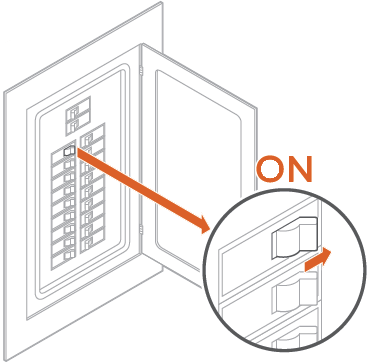
  1. Turn off power to the HVAC system at the circuit breaker.
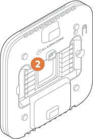
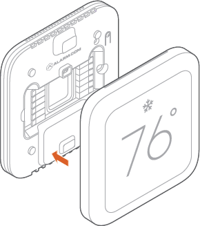
  2. Remove the Display.
  3. Hold down the terminal to remove the wire, remove the wire, hold down the opposite terminal, insert the wire fully.
  4. Reattach the Display to the Thermostat.
  5. Power on the HVAC system.

If this does not work, contact your local HVAC professional.

The Display is not working

The Display may not be configured to wake up when you approach. The Display may not be receiving power.

How To Resolve: Tap the screen to wake up the Display.

If you would like your Display to wake up in response to your movement in front of it, verify the settings in the configuration menu. Verify that the Display is powered.

  1. Remove the Display from the Thermostat.
  2. Verify the Thermostat LED is on. This indicates the Thermostat has power and should be able to power the Display.
  3. Put the Display back on the Thermostat.

Caution : If the Display is broken and cannot communicate with the Thermostat or is physically removed from the Thermostat, the HVAC control will not behave as expected. Please contact your HVAC professional to remedy the situation as soon as possible

Motion-detected wake sensor is too sensitive or not sensitive enough

The motion-detected wake sensor needs to be calibrated.

How To Resolve: To calibrate the motion-detected wake sensor:

  1. Tap MENU on the Display.
  2. Tap Installer Settings.
  3. Tap Advanced Configurations.
  4. Tap Calibrate Motion.
  5. Leave the area for at least 5 minutes for it to allow for calibration with no motion.
  6. Once calibration is complete, a prompt will display on the screen indicating whether or not the calibration was successful.

Note : If the thermostat is in a bedroom, it is recommended to turn the motion sensor off in the user settings. The motion sensor is sensitive enough to cause the display to stay on throughout the evening while people move in bed while asleep.

Dynamic backgrounds and/or salutations are not displaying correctly

Good Morning/Afternoon/Evening salutations and dynamic backgrounds require a clock report from the Z-Wave controller during the enrollment process.

How To Resolve: The local time is lost any time the thermostat or Display has power cycled for any reason. While the thermostat will request the time from the Z-Wave controller, it may not always receive the time from the Z-Wave controller.

In the event that the thermostat does not have a valid time set, a default background will be used with no salutations. Your dealer can send commands via Alarm.com to resolve.

The Display is unable to establish connection to the thermostat

The thermostat may be out of range of the Display or affected by interference from metal objects.

How To Resolve:

  1. Tap Retry on the Display to try connecting the same Display and thermostat again.
  2. If they are still unable to communicate, move the thermostat closer to the Display away from any metal objects, then retry again.

Note: After several retry attempts, there will be an option to reconfigure the connection. The Display will then list all thermostats within range to connect to

The Display says the wiring is invalid

The thermostat was wired incorrectly.

How To Resolve: Re-wire the thermostat following the on-screen instructions.

Hardware failure message displays on the screen

If the thermostat is experiencing hardware failure, one or more of the following messages will display on the screen:

  • D2 – Radar Failure
  • D3 – Temp/Hum Sensor Failure
  • D4 - Light Sensor Failure
  • D5 – Backlight Failure
  • D6 – Coprocessor Failure
  • D7 – Coprocessor Failure
  • D8 – Backplate Failure Detection
  • F0 – Temp/Hum Sensor Failure
  • F1 – Invalid Temp/Hum Data
  • F2 – Thermostat Memory Error
  • F3 – Thermostat Memory Error
  • F4 – Thermostat Memory Error
  • F5 – Relay Stuck Open
  • F6 – Relay Stuck Closed

How To Resolve: Reach out to your service provider

The thermostat is locked and cannot be controlled locally or remotely.

The thermostat was configured to be controlled remotely only, and then removed from the account before reverting the setting.

How To Resolve To manually remove a thermostat lock:

  1. Hold the Lock Icon on the thermostat screen for 10 seconds.
    Note : Power cycling the Alarm.com Smart Thermostat HD will not unlock the device.