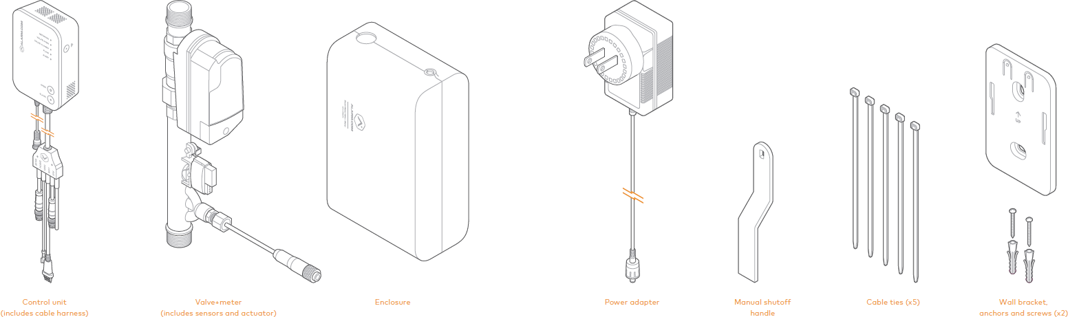
Installation location
Note : Water shutoff valves and leak detection devices should never be installed on a fire suppression system. If a fire suppression system is present, ensure the Smart Water Valve+Meter is installed downstream of the branch leading to the fire suppression system.
The Smart Water Valve+Meter must be installed:
- In a dry, indoor location.
- Downstream from the main shutoff valve and, if present, the pressure reducing valve.
- As close to the main shut-off valve as possible. The Smart Water Valve+Meter only monitors water activity downstream of the device.
- On a straight run of pipe approximately 14 inches (35 cm) long. The Smart Water Valve+Meter can be installed in smaller spaces by rerouting the plumbing.
- In compliance with all local plumbing and electrical codes.
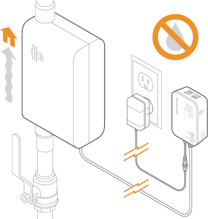
- Within 20 feet of a wall outlet. It is recommended to use an outlet with a ground fault circuit interrupter (GFCI).
- On water main distribution pipes 1 inch or less (ADC-SWM150) or ¾ inch or less (ADCSWM150-EU). For installation on larger pipe diameters, please review local plumbing codes, water demand, and hydraulic performance to ensure varying pipe sizes are compatible.
- With the control unit located above the valve+meter. Use drip loops wherever possible to avoid damaging the electronics in the event of a leak.
- So that it is easily visible and accessible.
Note : The Smart Water Valve+Meter features a backflow preventer. Ensure that there is adequate distance between the Smart Water Valve+Meter and the home’s hot water heater to allow for the expansion caused by the hot water heater. Additionally, consider installing an expansion tank downstream of the Smart Water Valve+Meter. It is not recommended to install the Smart Water Valve+Meter directly on the water heater supply line.
Installing the Smart Water Valve+Meter near a water heater
In some locations, the Smart Water Valve+Meter will need to be installed in close proximity to the water heater.
Because water expands as it is heated, if the meter is installed within several feet of the water heater, the pressure could build up and lead to the Temperature and Pressure valve on the water heater releasing to reduce the pressure.
This is not desired, so if there is no way to increase the distance between the water heater and the meter, it is advised to install an expansion tank on the inlet side of the water heater. This will allow the water to expand without creating a pressure spike that could damage the plumbing system. Expansion tanks should only be installed by a licensed professional.
Installation
Installing the Smart Water Valve+Meter
- Shut off the water supply line and drain all water from the plumbing system.
- Install the valve+meter in the water supply line using the appropriate fittings.
Important: Ensure that the device is installed in the correct orientation. An arrow embossed on the valve+meter indicates the correct direction of water flow.
Note: If soldering fittings or adapters, use caution to ensure that the valve+meter is not damaged by excess heat. Remove the valve+meter from the fittings prior to soldering, if possible.
- After installing the valve+meter, slowly turn on the main water supply and ensure there are no leaks originating from the valve+meter, connections, or surrounding pipes.
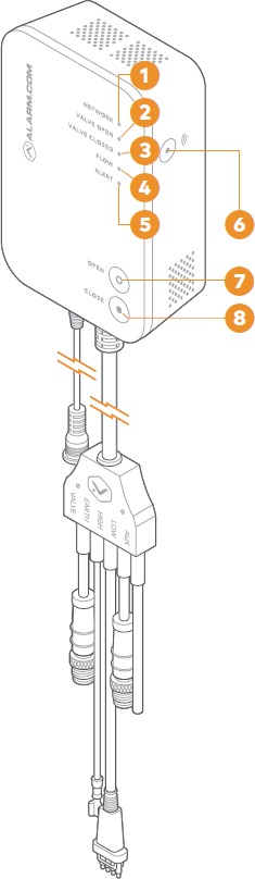
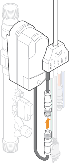
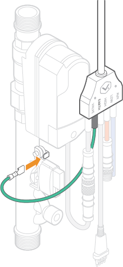
- Connect the cable harness to the valve+meter.
A. Connect the black VALVE cable to the actuator and tighten the screw connector to ensure a secure connection.
B. Connect the green GROUND cable to the ground cable connection on the valve+meter.
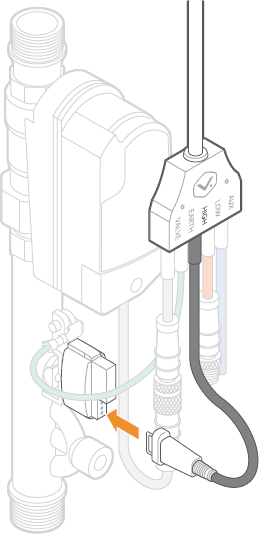
C. Connect the black HIGH cable to the high flow sensor and ensure that the tabs on the connector are fully engaged on the flow sensor.
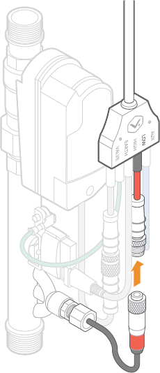
D. Connect the red LOW cable to the low flow sensor and tighten the screw connector to ensure a secure connection.
Note : The blue AUX cable is reserved for future use. It is recommended to leave this cable disconnected.
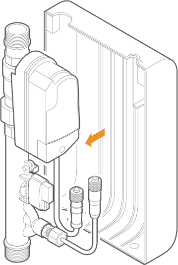
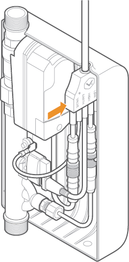
5. Install the enclosure (space permitting).
A. Attach SIDE A of the enclosure onto the valve+meter by clipping the valve+meter into the clips.
B. Secure the cable harness by inserting it into the cable harness holder on SIDE A of the enclosure. Ensure that all cables are inside the enclosure and connected properly.
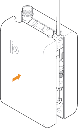
C. Attach SIDE B of the enclosure to SIDE A. When properly aligned, the two sides of the enclosure snap together using the integrated magnetic clasps.
- Use the included wall bracket and anchors (if applicable) to mount the control unit above the valve+meter, making sure the LEDs and buttons are visible and easily accessible.
- Connect the power supply to the power supply connection on the control unit. Tighten the lock screw to secure the connection.
- Plug the power supply into the nearest nonswitched wall outlet. Verify that the Smart Water Valve+Meter is powered by checking that either the Valve Open or Valve Closed LED is illuminated on the control unit. If no LEDs are illuminated, try a different power outlet.
- Test the Smart Water Valve+Meter to make sure it opens, closes, and detects flow
- Add the Smart Water Valve+Meter to the network
To test the Smart Water Valve+Meter:
- Fully open a tap or faucet downstream of the Smart Water Valve+Meter.
- Press the Close button and wait for the Valve Closed LED to turn solid.
- Check that the valve has closed by verifying that no water is flowing from the fixture opened in step 1.
- Verify that the Flow LED is not illuminated, indicating water has stopped flowing.
- Press the Open button and wait for the Valve Open LED to turn solid.
- Check that the valve has opened by verifying that water is flowing from the fixture opened in step 1.
- Verify that the Flow LED is illuminated when water is flowing.
- Close the tap or faucet opened in step 1.
- Verify that the Flow LED is not illuminated, indicating water has stopped flowing.