Sensors connected to the same COM terminal are triggered simultaneously

Since my Concord 4 system was installed 10 years ago, I’ve been living with the issue of 4 sensors (3 perimeter and 1 CO gas) being activated simultaneously whenever an alarm is triggered.

I’ve ignored the problem for years, and finally I took some time to investigate, and I now believe I’m on to something and need your help.

Investigation and Findings:

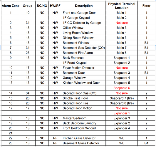
  1. I went through each terminal on my main board, the 8 zone snapcard, and 8 zone expansion module, to identify which terminal is connected which zone.

  2. I found that the 4 sensors that were simultaneously going off were connected to physically adjacent, consecutive terminals on the snapcard. (This was a big a-ha moment for me).

The 4 sensors are in bold below (basement door, garage window, kitchen window and door, and 2F CO).

Terminal labeled “Zone 6” CO 2F
Terminal labeled “Zone 5” kitchen window and door
COM for 4/5/6
Terminal labeled “Zone 4” garage window

Terminal labeled “Zone 3” basement door
Terminal labeled “Zone 2” CO 1F
COM for 1/2/3
Terminal labeled “Zone 1” backdoor

  1. I examined the wiring more closely, and realized the “basement door” com wire was connected to the COM terminal designated for 4/5/6. To clarify, the COM for 1/2/3 only had 2 wires connected, and the COM for 4/5/6 had 4 wires connected.

  2. I felt like a genius and proceeded to remove the basement door COM wire from the COM terminal for 4/5/6 and connected it to the first COM terminal (intended for 1/2/3). I was confident this was the issue that was hidden for 10 years!

  3. I powered the system and triggered the alarm by tripping a door. To my disappointment, the status showed that the “garage window” and “kitchen window and door” were open. (At least, the “basement door” did not pop up.) (Fyi, I had removed the 2F CO sensor from the panel temporarily, so that’s not in the investigation.)

Next Steps

What is my next course of investigation? Some questions I have:

  1. Could the COM terminal (designated for zones 4/5/6 on the snapcard) be causing the problem?
  2. Do I have to use designated COM ports for the sensors? (Or, do they just not want you to connect too many wires to one COM port?)
  3. On my 2nd expansion board (8 module expander), only 4 zones are used. Would moving the 3 problem zones to this different expander solve the problem?

I feel like I’ve made some progress here. Please let me know what else I could do at this point. Thank you.
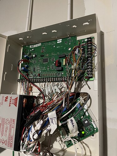
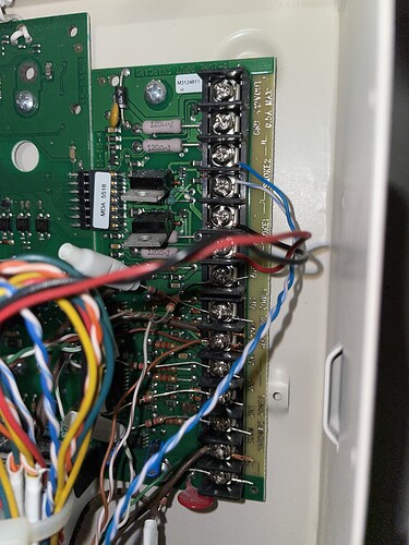
Going over that old post you linked, I think we’ll need a good image clearly showing the wiring connections for the zones in question.

Could the COM terminal (designated for zones 4/5/6 on the snapcard) be causing the problem?

Not in a normal circumstance. COM terminals are all internally linked to GND to my knowledge. There would need to be a separate wiring issue related to what’s going into that terminal or a problem with the terminals themselves.

Do I have to use designated COM ports for the sensors? (Or, do they just not want you to connect too many wires to one COM port?)

The COM ports are shared and shouldn’t cause what you are seeing.

On my 2nd expansion board (8 module expander), only 4 zones are used. Would moving the 3 problem zones to this different expander solve the problem?

Yes, that would be good at this point to rule out that first expander. Try connecting those problem zones to the other expander. I would do it one at a time though. Switch one over, test it, does it alarm by itself?

Switch a second one over. Test it, does it alarm by itself? If you get positive results from all three being switched over then there is something wrong with the prior wiring or the expander.

Do you end up with the same issue? If so, can you provide a photo of the new wiring?

Thanks Jason. The reason I was suspecting that the particular COM terminal might be problematic is that when I moved the “basement door” com wire from that problem com terminal to the one designated for 1/2/3, the “basement door” zone no longer gets activated when alarm is triggered.

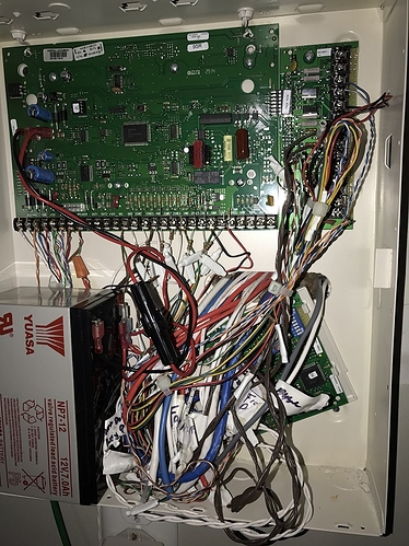
Full panel: main board, snap card on the right, second expansion module on the bottom.

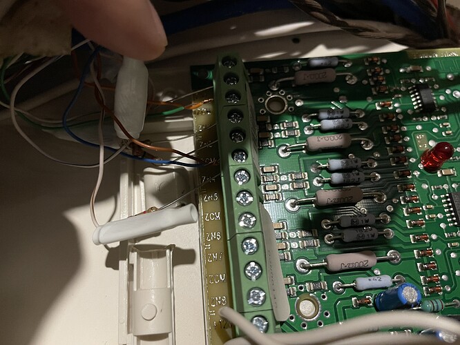
Snapcard (before I moved “basement door” from the 456 COM to 123 COM): If you look closely, you can see 4 wires connected to the 456 COM and only 2 on 123 COM. Again, after I moved the green wire from 456 COM to 123 COM terminal, that zone (basement door) is no longer triggered when alarm is tripped (I.e., working normally).

Second expansion module: First 4 zones are used. Maybe I can use the unused terminals for the three problem zones on the snapcard.

I do not see any obvious issues or shorts. I would recommend moving them one by one to the empty spots on the other expander and test for resolution.

One more thing, what is the thicker wire going into that troubled COM terminal? Can you confirm what circuit that is part of?

I am referencing the wire that is connected at the top of the COM terminal with 4 wires, the one with the thick sheath that appears to be a larger gauge.

I assumed (erroneously, I think) it was from the 2nd Floor CO detector that was alarming simultaneously with the other sensors sharing the COM port. Your question made me think about the wire itself, and I realized the 4-wire CO detectors in my house actually use green and white wires (and red/black for power).

So this thick sheathed brown wire you see on the troubled COM (and also another identical looking wire connected to the lower COM terminal where only 2 wires are connected) is most likely not for a CO detector.

It might be for motion sensors (maybe?), although I don’t know how to test for them. When I was checking the terminals by disconnecting each wire from the terminals to see which sensor would trip, the circuits with the thick wires (terminals labeled “Zone 6” and “Zone 2” on the top expander) did nothing (no indication on the keypad, no sound) when disconnected from the panel. I thought it was because I had deleted the 1F and 2F CO sensors from the panel.

(By the way, I tried to learn those CO sensors back into the system last night, but I couldn’t trip them. They are still at their EOL state, as I wanted to figure this out before ordering replacements. Could that be the reason they wouldn’t learn into the panel? I pressed the hush/test button for more than 10 seconds and nothing happened.)

My basement CO detector (terminal labeled “Zone 7” on the main panel) tripped immediately when I disconnected, and the wires for that were green and white.

You made me realize that untested assumptions can lead to wrong conclusions.

Yes, once I figure out what the think brown sheathed wires are for, I can try this. But now I think the 1F and 2F CO detectors are probably connected to terminals on the main board. (I have yet to test Zones 1-6 on the main panel.) I’ll go through all of them to complete the physical map of which terminal is for which sensor.

Thank you.

When I was checking the terminals by disconnecting each wire from the terminals to see which sensor would trip, the circuits with the thick wires (terminals labeled “Zone 6” and “Zone 2” on the top expander) did nothing (no indication on the keypad, no sound) when disconnected from the panel. I thought it was because I had deleted the 1F and 2F CO sensors from the panel.

That may be, the wire thickness just stuck out as different and if there are any questions about what it might be I would recommend testing without that connected.

If that circuit is removed from the terminal does the same issue occur with multiple alarms at once?

By the way, I tried to learn those CO sensors back into the system last night, but I couldn’t trip them. They are still at their EOL state, as I wanted to figure this out before ordering replacements. Could that be the reason they wouldn’t learn into the panel?

If they are expired then they will not be functional typically. Any expired detectors would need replaced.

Here to report some findings over the last few days.

The thick brown wire turned out to be physically wired to “Zone 5” terminal on the Snapcard. It was easily tested and identified as a wire for the “Kitchen Window and Door” zone. When disconnected and alarm tripped, all the same problem zones triggered together: “Kitchen Window and door” and “garage window.” If the “2F CO gas” zone had not been deleted, that would most likely trigger together.

Next, I finished physically testing every single terminal on my main panel, 8 zone snapcard, and the 8 zone expander. I also tried to make sense of some of the messy labels my installer taped on some of the cables coming out of the wall into the panel. Here’s what I have.

  1. I could not identify which terminals are for my 1F and 2F CO gas detectors.
  • 1F CO Detector by Garage
  • Second Floor Gas (CO)
  1. I could not identify the 1F and 2F motion sensors.

  2. Keypads: I have 3 keypads around the house. I found cables labeled 1F Garage Keypad and 1F Front Keypad and traced them to the physical terminals on my panel, but I could not identify the terminal or cable for the 2F keypad.

  3. Unidentified terminals:

  • “Zone 6” on the Snapcard: Whatever this is, it’s connected to the same problematic COM terminal with “Garage Window” and “Kitchen window and door.” That’s why I thought maybe this is the wire for the 2F CO detector (which alarms along with the other zones whenever alarm is tripped). But I am not sure.
  • “Zone 1” on the second Expander: Nothing happens when I disconnect the wire to this terminal.

If there’s one thing I learned, it’s that I should not make any uneducated guesses when I really don’t know anything, so I don’t want to make any now. I just want to know what the two unidentified terminals are for.


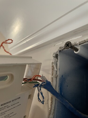
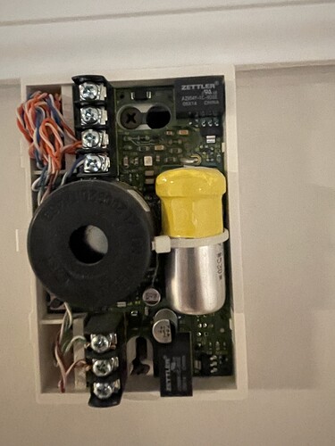
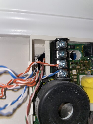
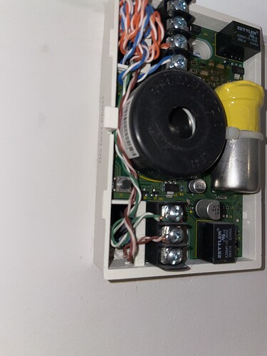
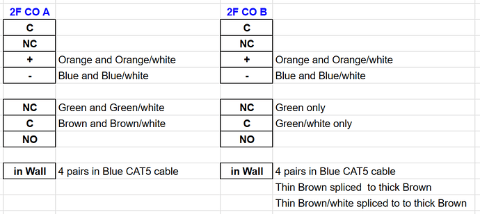
On a different note, in preparation for swapping out the expired CO detectors, I checked the wiring for the two CO detectors (presumably wired in the same zone) in the 2F CO zone. Here are the photos. I’ll call them “2F CO A” and “2F CO B.”

2F CO A
4 twisted pair ethernet cable comes out of the wall. Wired to + and - terminals and NC and C terminals.


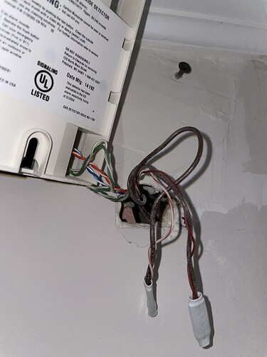
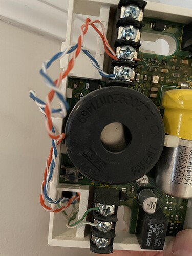
2F CO B
The wiring for this unit was slightly different. Only 3 pairs are used in the device. 2 pairs for the + and - terminals. But the green twisted pair is split, with only 1 wire going to NC and C. The brown pair of wires are crimped to different, thick sheathed wires in the wall.


Questions:

  1. The CO detectors in my house are all wired NC. Is that ok (if not typical)?
  2. Does the wiring for this 2nd Floor zone look ok? Is it ok for the green pair to split to NC and C terminals on detector B, but on detector A, both green and brown pairs are used?
  3. What would the wiring look like on the panel side for this CO zone? Any clue I can follow?

Going back to the simultaneous alarming issue, if I want to start moving the wires from the problem terminals on the snapcard to the empty terminals on the second expander, what is the proper order to follow?

  1. Should I first “delete” the sensor in Programming?
  2. Then “Learn” it in Programming under a different zone number after connecting the wires to the other expander?

If I simply physically move the wires, will the system recognize the sensor without any programming (without needing to delete and learn again)?

Thank you.

The CO detectors in my house are all wired NC. Is that ok (if not typical)?

That’s ok, the Concord 4 wired zones can be programmed as either.

Does the wiring for this 2nd Floor zone look ok? Is it ok for the green pair to split to NC and C terminals on detector B, but on detector A, both green and brown pairs are used?

That depends how A is wired. I can’t tell exactly in the photos, are the NC and C terminals wired with both of the same color in one and both of the same color in the other?

Or are they split? Brown and green/white in one, Green and brown/white in the other? I am guessing they are split like this.

What I would guess from the photos is that it might be two CO detectors wired in parallel. However that would require them to be NO zones, not NC. NC and Parallel wiring would mean that both have to activate in order for the zone to trip. It is possible someone wired it that way manually due to false alarms or something, but I wouldn’t recommend it.

My guess is that the greens on A go to the terminals on B, not back to the panel. But that is a guess, it would be necessary to try shorting those wires and read them with a multimeter in different states to tell. Short the green wires at one detector, read the value at the other, are the green wires reading closed with no resistance? Remove the short, then test again. Does the meter then show open?

The brown pair of wires are crimped to different, thick sheathed wires in the wall.

Are those the thick wires that were in the panel terminals?

What would the wiring look like on the panel side for this CO zone? Any clue I can follow?

If the wire is unbroken you would look for the browns at the panel. Judging from the photos, if it is wired the way I think it is, those thick wires we pointed out before are probably the CO detectors. The browns are spliced there behind B.

Should I first “delete” the sensor in Programming? Then “Learn” it in Programming under a different zone number after connecting the wires to the other expander?

Yes, delete the zone associated with the current sensor terminal. Then move the wiring to the new terminal and program that new zone in.

Sensor programming steps start on page 5 of the manual here.

If I simply physically move the wires, will the system recognize the sensor without any programming (without needing to delete and learn again)?

No, the new zones would need to be programmed.

I could not identify which terminals are for my 1F and 2F CO gas detectors.
1F CO Detector by Garage
Second Floor Gas (CO)
I could not identify the 1F and 2F motion sensors

Are those definitely all wired sensors? It is not uncommon on older systems to have one or two sensors replaced over time with wireless due to various troubles.

Actually, A’s NC and C terminals are wired to same color pairs as below.

Here’s how I would describe the wiring in plain English.

Not sure, because the same-looking thick brown wire pairs are used for various zones and connected to various terminals in the panel. For sure, the thick wire you asked about (for “Zone 5” terminal on the expander SnapCard) is not the 2F CO wire. It was for “Kitchen Windows and Door.” I tested it multiple times to verify.

It is possible that the thick brown wire from the 2F CO detector is in the panel but I just haven’t identified it. But the strange thing is that neither of the unidentified terminals in the panel is connected to a thick brown wire. “Zone 6” terminal on the Snapcard (next to the problem COM terminal) is connected to Brown/White, and the “Zone 1” terminal on the second expander is connected to Orange/White or Green/White. All four pairs of the same CAT5 cable are used for Zone 1 through 4 terminals on the second expander, presumably going to the second floor perimeter zones.

Thank you for confirming. That wiring would suggest my assumption is wrong.

It would appear that those two CO detectors are either not wired to the same zone, or are wired in series back at the panel or somewhere else in wall.

To identify where those wires are going it will take trial and error testing the unknown wires.

Just to be sure those two CO detectors aren’t miswired by the installer, Try removing those green wires from both detectors and test them with a multimeter. Attach the two leads of the multimeter to the two wires. Short them at one end, test the other end. Is it closed? If it is, open the short and test again. Does it report open?

Since those CO detectors are likely all expired and need to be replaced, it may be best to switch to wireless options to eliminate wiring issues. That would ensure any issue causing the simultaneous activation of them can’t happen again.

This may also be a good idea if moving the wired sensors to the different zone expander board results in the same simultaneous activation. That would suggest an unknown wiring issue is the cause. Replacing those sensors with wireless sensors would get around the questions with old wiring.

I saw some spliced wires in the panel box before the wires are connected to terminals. I’ll do some more digging. At this point, it’s become more of a quest rather than a practical use of time! :slight_smile:

I have a multimeter, but I’m not 100% sure exactly how I should test. (For example, there are Green and Green/White on one detector and just Green on the other on the NC terminals. And will my multimeter have the length to reach the two detectors – maybe 20 feet apart?) Let me do the following first and come back to the continuity test.

Since I need to replace 4 (2 of them in the same 2F zone and part of the simultaneous triggering problem), maybe I’ll buy 2 first for testing for the 2F zone, and if I fail, I’ll use them for the other zones on 1F and basement.

Sounds good. I will move the two perimeter sensors to the other expander board and see if they still activate together (before I even deal with the CO detectors).

I’m just baffled as to why, when I moved the Basement door sensor (previously it was connected to the problem COM terminal and was simultaneously activating) COM wire to the other COM terminal, that sensor stopped activating with the other problem sensors.

Thank you Jason for the continued guidance.

I’m just baffled as to why, when I moved the Basement door sensor (previously it was connected to the problem COM terminal and was simultaneously activating) COM wire to the other COM terminal, that sensor stopped activating with the other problem sensors.

It doesn’t make a lot of sense to me either. I’m trying to imagine a scenario which would result in that happening. It is very likely there is a problem with the board. Moving the zones would be the best test for that.

I have a multimeter, but I’m not 100% sure exactly how I should test. (For example, there are Green and Green/White on one detector and just Green on the other on the NC terminals. And will my multimeter have the length to reach the two detectors – maybe 20 feet apart?) Let me do the following first and come back to the continuity test.

When I suggest the continuity test, it is just on the off chance that the installer miswired what they intended as a parallel circuit. I only suggest it since there was only one zone apparently for those two sensors. It could be that one was just removed/deleted from the panel.

To test I would remove the green and green white at both sensors. At one those are in the NC and C terminals, at the other they are both in NC.

  • At one sensor location put the Multimeter leads on the green and green white wires.
  • At the other sensor location, twist the green and green white wires together.
  • At the multimeter, with one lead on green and one lead on green white, is the circuit closed?
  • If yes, go to the other sensor and untwist those wires so that are open.
  • At the multimeter is that circuit now open?

Crystal clear now. I can do that. Thank you!

Ok, I’ll move the zones and test.

Finally got around to continuity testing on the CO detectors in the same zone, and the results are confusing. One caveat: This CO gas zone was deleted from the panel, but I did not turn off the power to the panel for this test. If I need to rerun tests with power off, please let me know.

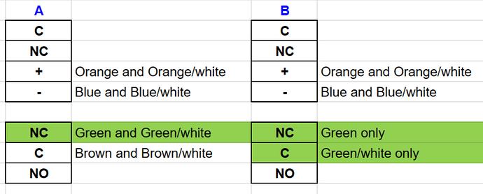
As a reminder, below is the wiring for the two CO devices in the same zone, and we are testing continuity on the green and green/white wires.

First, I put the Multimeter leads on the green and green/white at device A. Tests showed circuit closed whether the wires at B are twisted or untwisted.

image

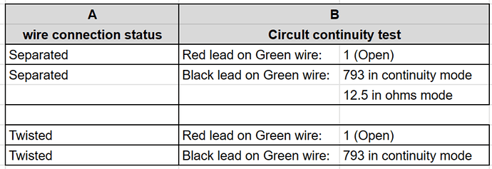
Next, I put the Multimeter leads on the green and green/white wires at device B. The strange thing here I discovered by chance was that the multimeter reading was different depending on which color lead was connected to which wire.

What do you make of these test results?

I moved one of the zones (Kitchen Window and Door) connected to the problem COM terminal to a free terminal on the other expander, and it no longer alarms when other zones are tripped. I tested another zone (Garage window) connected to the problem COM terminal by connecting its COM wire to a different COM terminal on the same snapcard expander, and that zone stopped activating simultaneously. So, based on my limited testing, somehow, whatever sensor is connected to the problem COM terminal alarms simultaneously whenever an alarm is triggered.

For next steps, I will move the two perimeter zones to the other expander, and then decide what to do with the CO zone above.

One quick question about learning in the CO gas zone to the panel: What is the correct way to learn in a CO zone when there are two CO devices on the circuit? Would triggering one of them (by pressing the test button when the panel is in Learn mode) be enough? Will the second device be learned in along with the first one?

Thank you.

First, I put the Multimeter leads on the green and green/white at device A. Tests showed circuit closed whether the wires at B are twisted or untwisted.

Just to be sure, you had those wires disconnected from the terminals at both CO detectors right? Just wanna be sure they were not tested while wired into the CO detector terminals.

What that means is those two CO detectors are likely not on the same zone.

I think to identify exactly which sensor(s) are connected I would next recommend powering down the panel, then pull those CO wires from the zone terminals, and test between them with the multimeter.

Are they closed? If so, pull the wire(s) in the C terminal of one of the CO detectors. Does the multimeter show the zone wires open after that?

Reconnect the C terminal wire(s) and make sure the multimeter shows closed. Go to the other CO detector and pull the C terminal wire(s). Does the multimeter show the zone wires open after that?

This is to test if both of those sensors are on that one zone circuit back at the panel. Based on the available testing so far I would expect them not to be.

One quick question about learning in the CO gas zone to the panel: What is the correct way to learn in a CO zone when there are two CO devices on the circuit? Would triggering one of them (by pressing the test button when the panel is in Learn mode) be enough? Will the second device be learned in along with the first one?

If they are wired properly there is nothing special needed, you would just program the hardwired zone into the panel. Either can be used to trigger it. They would be wired in series if they are NC and when either triggered, the zone would read an open circuit.

Yes, those wires (green and green/white) were disconnected from the device terminals.

Ok, I’ll try this. I never verified that the wires connected to the problem zone terminal on the panel are actually CO wires, but I’m assuming they are, given that this CO zone would activate simultaneously with the other sensors connected to the same COM terminal on the panel. Anyway, I’ll test and report back.

Here are the results of the continuity test with the panel powered down, with the multimeter on the panel side.
image

Now, while the 2F CO zone terminal wires (zone and COM wire) were pulled from the panel, I thought back to your earlier comments.

So, while I had those panel zone wires removed, I tested for simultaneous alarm activations. And, I found that a simultaneous alarm activation only happens when the CO zone COM wire is connected to the panel! That is, an alarm would trigger for any zone that is sharing the same COM terminal as the 2F CO zone.

This finding (I blame a bad case of confirmation bias on my part) reminded me of another earlier nugget of wisdom from you below.

I suspect there’s some faulty wiring somewhere in the wall. The 2F CO zone wires at the panel are not the same as any of the wires found on the device side. So, after this fun journey, at long last, I think I’m going to follow your advice below.

As I prepare to install the IQ CO Detector, I have a couple of questions:

  1. Is the wireless signal typically strong enough to reach from the panel (down in the basement) to the 2nd floor where the detectors will be installed?

  2. I assume I would remove the expired wired detectors and simply cover the area with the new IQ detectors, correct?

  3. On the panel side, do I need to find the power wires that were used to send power to the wired detectors and pull those?

Thank you for everything.

Thank you for describing that testing, and I am glad to hear the cause has been isolated.

Is the wireless signal typically strong enough to reach from the panel (down in the basement) to the 2nd floor where the detectors will be installed?

In a typical home yes it is usually fine, the Concord 4 has large RF antenna which attach and come out the top of the panel. From your earlier photos it looks like the antenna sheathes were installed properly.

I assume I would remove the expired wired detectors and simply cover the area with the new IQ detectors, correct?

Yes, you could remove the low voltage CO detectors and replace them with the wireless in the same location.

On the panel side, do I need to find the power wires that were used to send power to the wired detectors and pull those?

Yes, disconnect the aux + and - wires powering those old CO detectors first.