Physical installation of the PG9303 PowerG wireless door/window sensor should follow the manufacturer’s instructions found in the product installation manual. Installation steps from the PG9303 manual are below:
Installation Notes:
To comply with FCC and IC RF exposure compliance requirements, locate the device at a distance of at least 20 cm from all persons during normal operation. Do not co- locate the antennas used for this product, or operate them in conjunction with any other antenna or transmitter.
The PG9303 should be installed in non-hazardous indoor locations only.
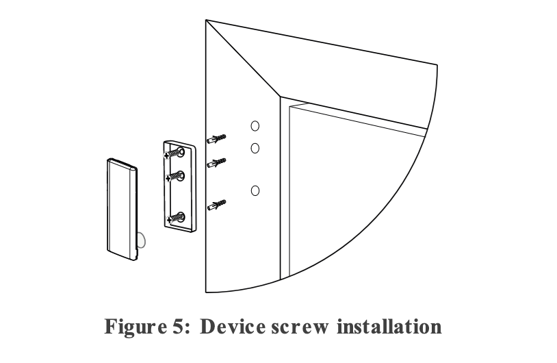
For UL installations, use the screw installation method, as UL certified devices must be mechanically secured.
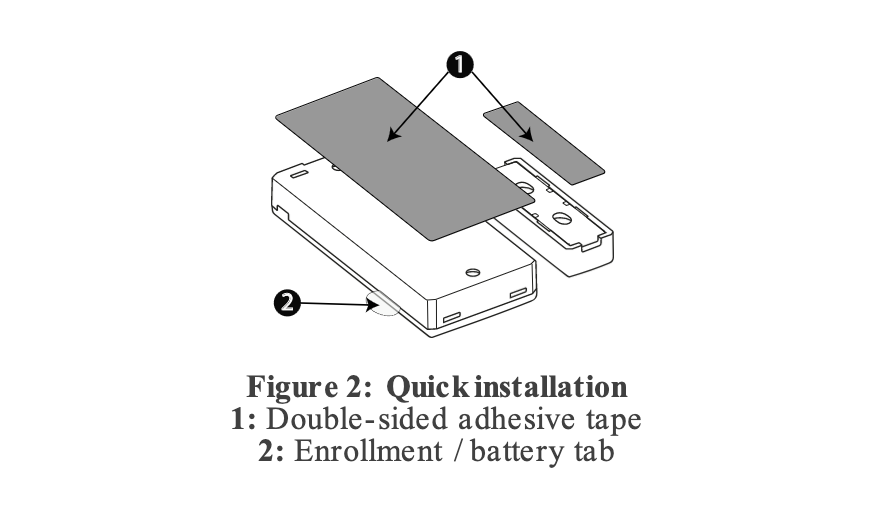
Mounting the PG9303: (Adhesive Installation)
Peel the release liners off the two strips of double- sided adhesive tape and attach the tape to the back of the device and the magnet. See Figure 2-PG9303.
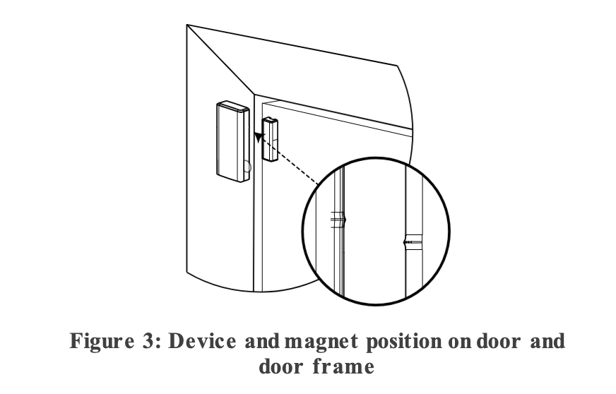
Place the device on the frame of a window or door and place the magnet on the moving surface of the door or window itself, directed according to the location marks. See Figure 3-PG9303
To ensure proper alignment so that the sensor can open and close properly, see Typical reed switch positions.
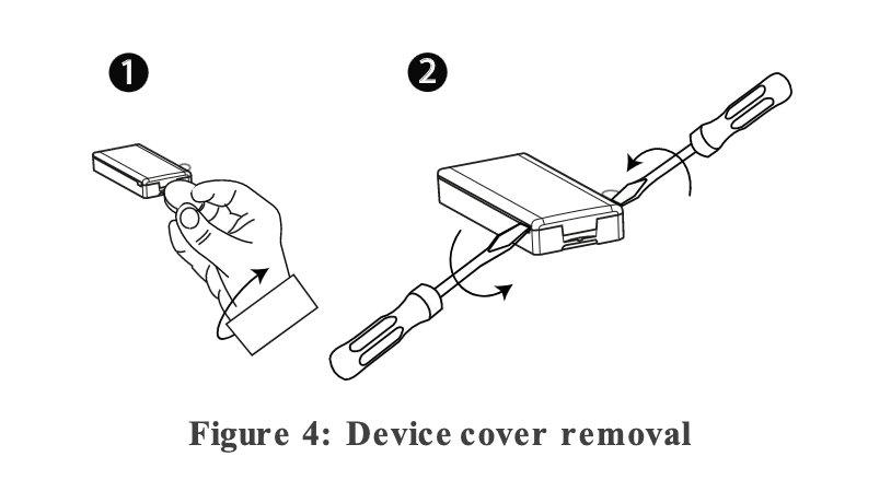
Insert a coin in the slot and twist to remove the cover. See image 1 of Figure 4-PG9303. If a coin is not available, insert a 4 mm flat screwdriver into each slot of the plastic cover and twist to open each side. See image 2 of Figure 4-PG9303.
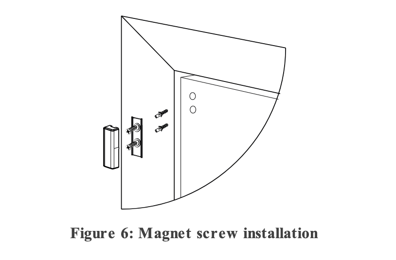
Screw the device base onto the door frame. See Figure 5-PG9303.
Screw the magnet base on to the door, aligning it with the line on the device. See Figure 3-PG9303.
To ensure proper alignment so that the sensor can open and close properly, see Typical reed switch positions.
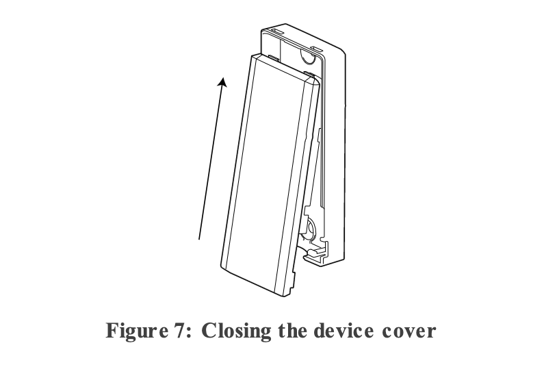
Clip the covers on to the device and magnet base. See Figure 7-PG9303)