Hello,
We just installed our SEM300 module into our Vista20P system. When we log into Alarm dot com, we get an error message:
“Modem-Panel Comm. Error”
Any advice?
Allen
Hello,
We just installed our SEM300 module into our Vista20P system. When we log into Alarm dot com, we get an error message:
“Modem-Panel Comm. Error”
Any advice?
Allen
It is not flashing. It is solid red.
#1 light solid red
#2 and #3 lights off
#4 light solid yellow
#5 light solid blue
We’ll need to reach out to Alarm.com to troubleshoot this further. We’ll follow up here shortly once we have heard back.
I am not seeing that trouble condition currently on your account, however no zones have been shared through the SEM yet either.
Can you confirm if you see the same LED behavior locally? If you are still having trouble, can you please send a PM with photos of your SEM and panel wiring?
Jason,
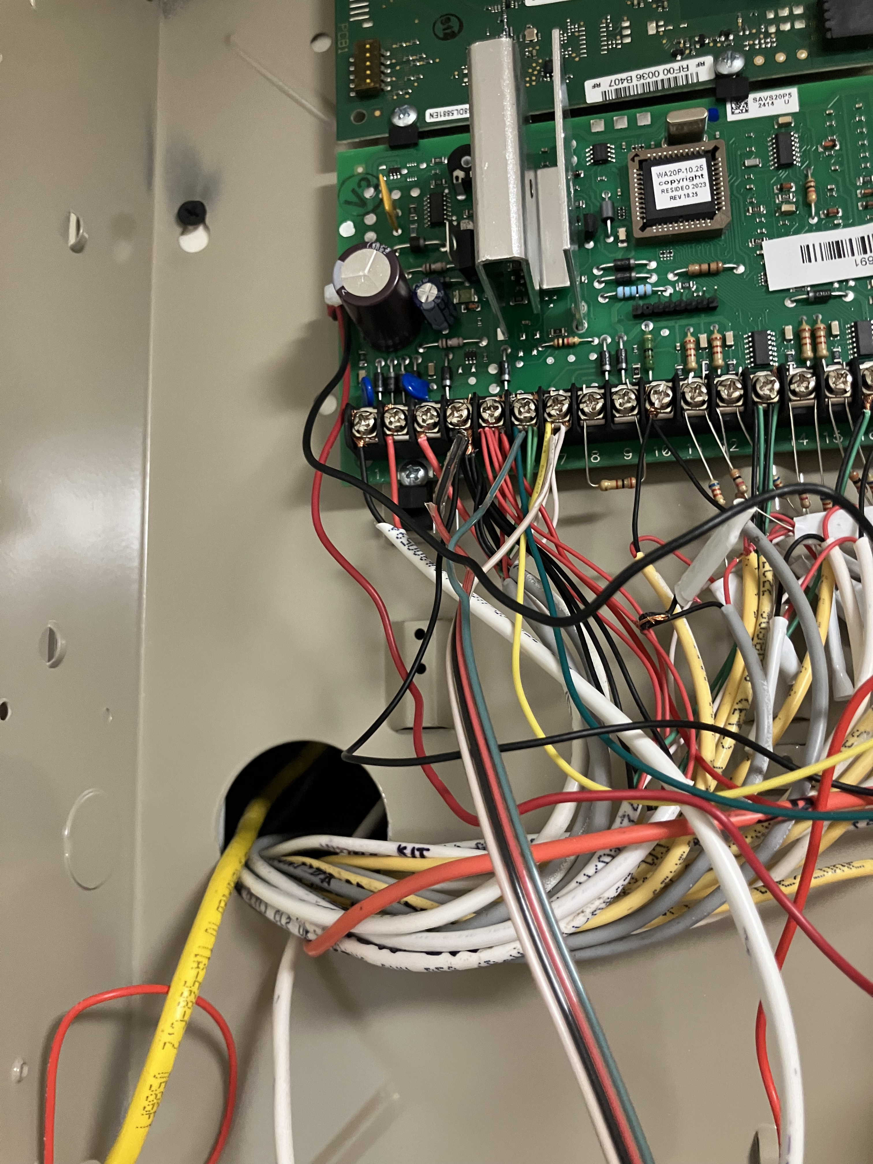
We connected the SEM300 module to the security panel circuit board using a solid copper wire bundle in which white substitutes for yellow. The red wire in the bundle was not used; a separate red wire connects the SEM300 circuit board directly to the battery.
Everything is “local,” as we have no evidence that the SEM300 module is communicating with alarm.com.
I have a 60-second video which I apparently cannot upload. For the first 45 seconds, the pattern is as described previously: 1=solid red, 2=off, 3=off, 4=solid yellow, 5 = solid blue.
At about 45 seconds, 4 goes dark. About a second later, 2 & 3 are green and 4 lights up yellow. The pattern is 1=red, 2=green, 3=green, 4=yellow, 5=blue.
Next, 1-4 go dark, 5 remains blue.
After a second or two, 1 lights up red. The pattern is 1=red, 2-4 dark, 5=blue.
Very quickly, 1 goes dark, 2 lights up green, 5 remains blue. Then 2 goes dark and 3 lights up green. Next 3 goes dark and 4 lights up yellow, then 4 goes dark. At this point, only 5=blue is lit.
Then 4 lights up yellow, then 1 lights up red. All of these changes take place during a period of about 10 seconds. At the 55 second point on the video, we are back to the original pattern: 1=red, 2&3 are off, 4=yellow, 5=blue.
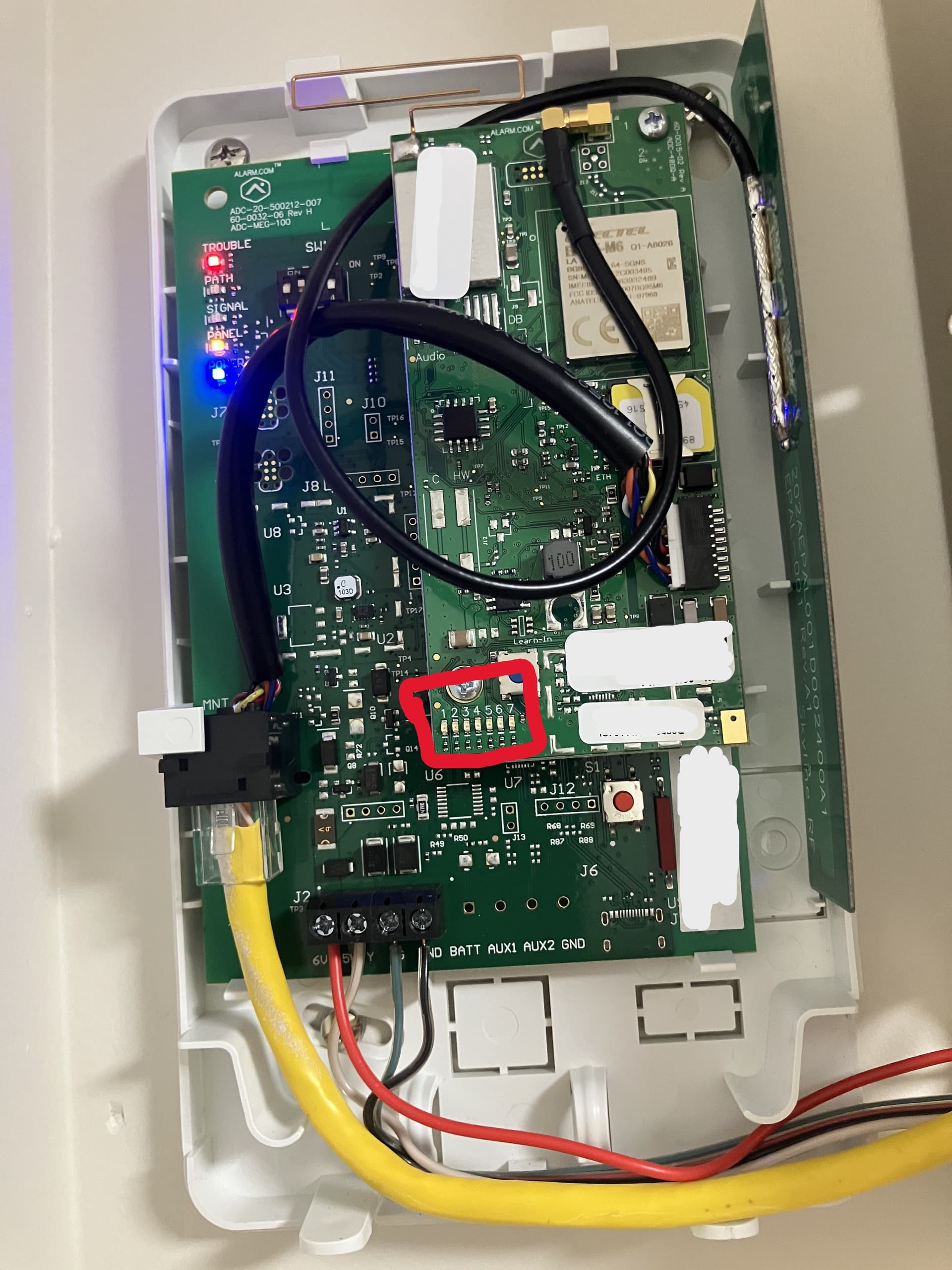
Can you confirm the flashing patters on LED 1 that I marked with a red box in the picture?
It looks like the panel hasn’t synced up correctly with SEM. Can you make sure that keypad 23 is enabled in programming?
To enable keypad 23:
Also, can you default the installer code to 4112… We would like to make sure the SEM and panel Sync up perfectly.
To do this:
After performing these steps, can you power cycle the panel by unplugging the transformer and unplugging the battery from the panel. Then reconnect the battery first followed by the transformer.
Do not touch the keypad as it should start to scroll through programming and create a few beeps. This can take up to 20 minutes.
Prior to attempting to enable keypad 23:
For the highlighted LEDs, there is a repetitive pattern which lasts for 9 “blinks.”
blink #1
1= red blinks on
4=green comes on solid (duration = 4 blinks)
5=yellow blinks on
blink #2
4=green remains on solid
5 = yellow blinks on
blink #3
4=green remains on solid
5 = yellow blinks on
blink #4
4=green remains on solid
5 = yellow blinks on
blink #5
yellow blinks on
blink #6
yellow blinks on
blink #7
yellow blinks on
blink #8
yellow blinks on
blink #9
all lights are off
blink #10 = blink #1, i.e., 9-blink pattern repeats.
Followed your instructions to enable keypad 23
Entered installer code
pressed 800
display read 20
pressed *196
display read 197
display flashed 00
keypad beeped three times
pressed *99
SEM300 patterns look the same.
Based off of the description, it looks like LED 1 flashes only once and then repeats. This does mean that the SEM is having trouble communicating with the Panel.
Did you attempt the installer code change?
The installer code is currently 4112.
Okay, try changing it to something that doesn’t have consecutive number or repeated numbers. Then power cycle the system and wait to see if it scrolls through programming.
If it does, you can change the installer code back once it’s done.
OK. I changed the installer code to something that does not have consecutive or repeated numbers.
I powered down the system, waited 5 minutes, reconnected the battery, and plugged in the AC power. The keypad read d1 and not ready.
I came back after about 20 minutes. The keypad read ready.
The light patterns on the SEM300 module are exactly the same as they were before. Next step?
Can you let me know what the devices you have on the panel? Zone expanders, keypads, etc.
Do you currently have an a phone line connected to the panel? Please remove the phone line from the panel if there is one. Then remove existing phone numbers from programming by:
First, lets try changing a few programming changes:
Next, try sending a cellular communication. You can to this by
Vidail,
We can work on the alarm reprogramming this afternoon.
In the meantime, I can provide the following information:
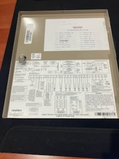
The devices on the panel are 2 keypads and 1 wireless antenna. The windows, doors and motion sensors are hard wired except for one door on zone 17. The wire to the door was corrupted during construction and rewiring was impractical. This is why we have one wireless zone and a wireless antenna. A photo of the wiring diagram (with the zone list) is attached.
There is no phone line attached to the panel. We purchased an AT&T-compatible SEM300 module (the AT&T signal is much stronger than the Verizon signal). We will start by removing any existing phone numbers from the system, and then follow your instructions for the reprogramming.
Allen
We tried all of the programming codes above. Now, we are seeing “6F” or “bF” and “FC” as error codes on the keypad. Still do not see any kind of zone scan, and the SEM300 is still showing the “trouble” LED (top), the “panel” LED (second from bottom), and the “power” LED (bottom) constantly illuminated.
We changed the installer code back to 4112. Also, if it matters, we have 2 non-alpha keypads, which seem to make *29 programming more difficult because there is no feedback. Do we need to replace one of the keypads with an alpha keypad?
What zones will you be reprogramming?
bF means that the panel is having issues uploading a backup and FC means failure to communicate. Was there a previous cellular communicator on this panel before the alarm.com cellular communicator?
There was no previous cellular communicator on the panel. It is a new installation that has never been connected to an alarm monitoring service.
Vidail,
We reprogrammed zones 41, 42, 43, 48 and 196, as you had recommended. For all of those zones, the keypad beeped three times when we reprogrammed the zone, so we think we were successful.
We made several attempts to reprogram zone 29, but are not sure if we succeeded. We have a 6150 non-alpha keypad, so there is no audio or visual signal when the zone is reprogrammed. Also, based on programming instruction manuals found online, some versions of the 6150 keypad use different sets of keystrokes to exit and save zone 29 reprogramming. We tried several keystroke combinations to exit *29 reprogramming, but nothing caused a change in the light patterns in the SEM300 module (the trouble light has always stayed on). The only possible indicator of success is that the bF error popped up after reprogramming *29, and has never gone away.
The company that installed the low voltage wiring and the Ademco Honeywell alarm system did not provide a programming instruction manual. I called them and asked if they could provide one, and they promised to look in their records to see if they could identify that version of the 6150 keypad that they installed, but I haven’t heard back. They are unwilling to troubleshoot the system unless we hire them to monitor alarm events.
I am not an electronics person, but here is where I think we may be:
We are confident that the wiring for the local system is correct (keypads, Ademco Honeywell control panel and circuit boards, wireless receiver for zone 17) because the system works locally. It fails only when we try to set up data communications with Surety.
We are confident that the wiring for the SEM300 module is correct. You reviewed that from photos we sent and did not advise us of a problem.
We may have failed to properly reprogram zone 29. Do we need to replace the non-alpha 6150 keypad with an alpha keypad (It would be a 6160, I think)?
There may be a problem with the SEM300 module that prevents it from receiving data from the Ademco Honeywell control panel. Do we need to send the SEM300 back to alarm.com for a replacement?
There may be a problem with the Ademco Honeywell control panel that prevents it from sending data to the SEM300 module. Do we need to replace the main control panel as well as the keypad?
Do you have any suggestions?
Allen
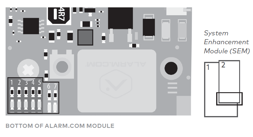
There should be dip switches on the board. Can you confirm 2 and 3 are on?
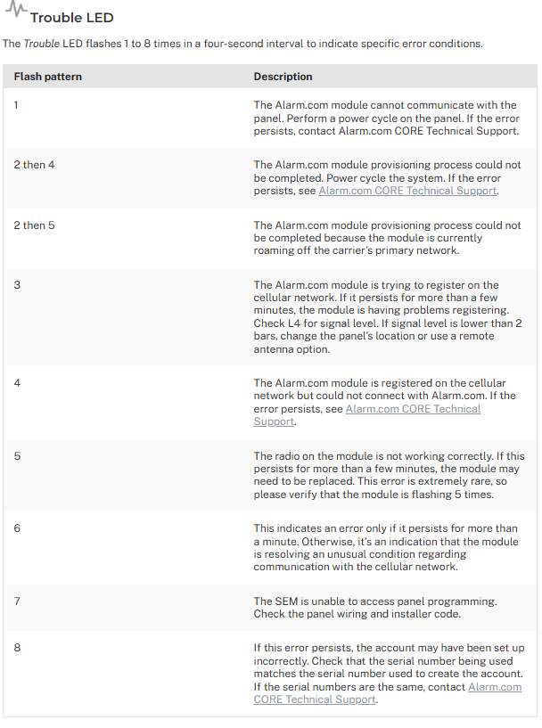
I just want to double check the LED Pattern of the trouble light on the top left. This trouble LED blinks once, pauses, blinks once, pauses, and just repeats, correct?