Important: A service package that includes Video Analytics and the Doorbell Cameras add-on is required to enroll the ADC-VDB780B.
**ADC-VDB780B on firmware version 2.4.1.092+ and included accessories
Drill/Screwdriver
Level
Pencil
Wi-Fi connection to broadband (Cable, DSL, or Fiber Optic) internet
A computer, tablet, or smartphone with Wi-Fi
**Important: The ADC-VDB780B must be on firmware version 2.4.1.092+ to be installed using Doorbell Direct with the IQ Panel 4/IQ4 Hub/IQ4 NS and IQ Wi-Fi 6. Devices below that firmware must be connected to an Alarm.com access point, such as a W115C or SG130, to update the firmware before use with a panel.
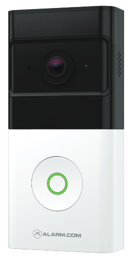
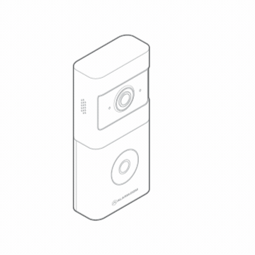
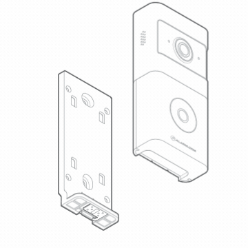
Remove the Wireless Video Doorbell (VDB780B) from the packaging.
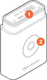
Separate the battery pack from the VDB780B body.
Activate the battery by plugging in the Micro USB charger to a wall outlet and connecting it to the battery.
Check the top of the battery pack for a blue protective film. If present, please remove the film and discard it.
Press the doorbell button on the front of the battery. If the button LED alternates between red and blue, the battery pack must be recharged prior to completing the installation.
If the button LED isn’t alternating blue and red, reconnect the battery pack to the VDB780B body.
After the button LED stops flashing red, press and release the doorbell button and ensure the LED lights up red.
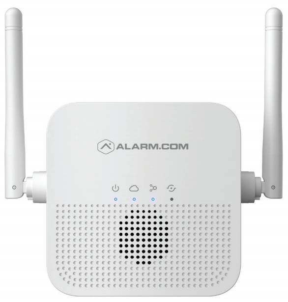
Connect the Wireless Video Doorbell to the Alarm.com Smart Chime
Verify the Wireless Video Doorbell (VDB780B) is less than 10 feet away from the Alarm.com Smart Chime (W115C).
Verify that the W115C has been installed and associated with an account.
To enable WPS mode, press and hold the VDB780B doorbell button firmly for greater than 30 seconds. The LED will begin flashing blue.
Press and release the WPS button located on the side of the W115C to enable WPS mode. The WPS LED will begin flashing rapidly.
If the pairing is successful, the W115C Devices LED will quickly blink 3 times, and the VDB780B LED will begin blinking red and then turn solid green.
Connect the Wireless Video Doorbell to the same network as the IQ Panel 4/Hub/NS:
The VDB780B does not use the IQ Panel 4, IQ Panel 4 Hub, or IQ 4 NS panel as an access point but works in tandem with it as long as both devices are on the same network.
Note: The panel must be installed first. The panel must also be on firmware version 4.5.0+
Using AP Mode:
The camera is in Access Point (AP) mode when the button LED is blinking white. If necessary, access AP mode by holding down the doorbell button for 46-60s and release when the LED turns to blinking white.
Using a Wi-Fi-capable device (e.g., smartphone or computer), find and connect to the camera’s network; the SSID should have the format ADC-VDB780B (XX:YY:ZZ) where XX:YY:ZZ is the last 6 characters of the MAC address, which is printed on the included reference card.
On the same device, open a web browser and enter http://vdb780binstall or 192.168.1.1 in the web address field. Follow the on-screen instructions to add the ADC-VDB780B to the same network as the IQ panel.
Verify the LED turns solid green, indicating the connection is complete.
Using WPS Mode:
Put the router the IQ panel is connected to into WPS mode. This will depend on the model of the router.
Put the VDB780B doorbell into WPS mode by pressing and holding the doorbell button firmly for greater than 30 seconds. The LED will begin flashing blue.
If the pairing is successful, the the VDB780B LED will begin blinking red and then turn solid green.
Enroll the Wireless Video Doorbell to the Account
Once the ADC-VDB780B is connected to the ADC-W115C, it can be enrolled to the Alarm.com account using the Alarm.com mobile app, or Alarm.com Website
Alarm.com Mobile App
Log into the Customer app.
Tap Video.
Tap Settings Gear
Tap Add Video Device.
Tap ADC-VDB780B.
Follow the on-screen prompts for installing the video device.
Alarm.com Website
In an internet browser address bar, enter www.alarm.com/addcamera and log into the customer account. Alternatively:
a. Log into the Alarm.com Website.
b. Click Video.
c. Click Settings.
d. Click Add Video Device.
Find the ADC-VDB780B in the list or enter its MAC address and enter a name for the video device.
Click Install to begin installing the ADC-VDB780B.
Follow the on-screen prompts for installing the video device.
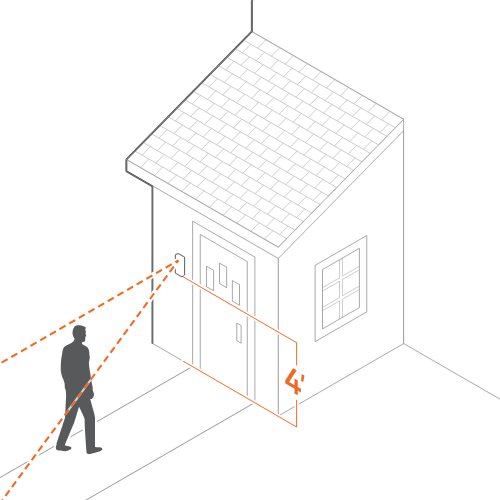
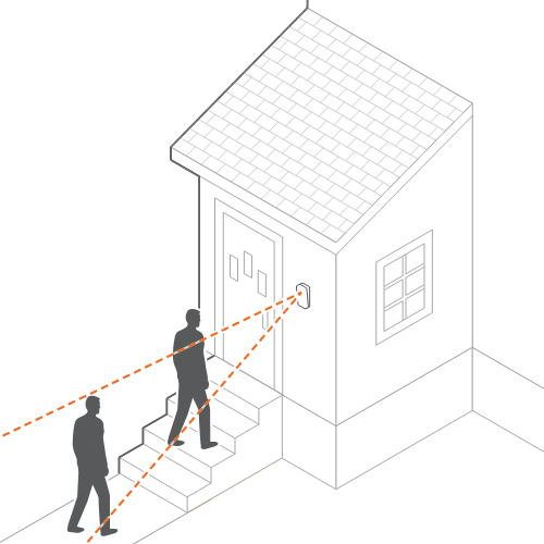
Identify a location on the side of your doorframe to mount your Wireless Video Doorbell (VDB780B). We recommend a position approximately 4 feet above the ground for an optimal field of view.
Place the mount at your desired location.
Use a level to ensure the mount is parallel to the ground.
Use a pencil to mark the two holes of the mount.
Tip: If you have someone to help you with the setup, use the Mobile App or Alarm.com Website to start a live stream. You can place the VDB780B over your planned mounting position to assess the field of view before you start drilling.
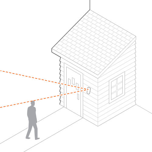
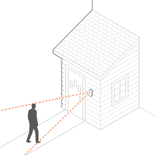
There are two common mounting areas that can lead the Wireless Video Doorbell to be misaligned. The included 10º tilt wedge mount may be required to point the Wireless Video Doorbell properly.
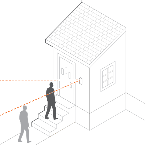
Mounting on an elevated entryway
If the installation location has stairs or a ramp leading to the entryway, a tilt wedge will likely be needed to help focus the Wireless Video Doorbell on the visitors’ approach path.
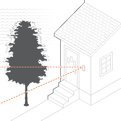
A doorbell mounted on an elevated entryway may wake up too often due to constant or uninteresting motion.
Install the 10º tilt wedge mount included in the doorbell’s packaging to focus the PIRs downward to reduce unwanted wake-ups, and improve recorded clips.
Use a 1/4” drill bit to create appropriately sized holes for the supplied anchors at your marked locations.
Insert the anchors.
Screw
Place the mount over the two anchors.
Use the supplied screws to secure the mount in place.
Attach the Wireless Video Doorbell to the Mount
Align the prongs on the back of the Wireless Video Doorbell (VDB780B) with the 4 rectangular slots in the mount.
Push the VDB780B into the slots and slide down, until the device clicks into place.
Slide the latch on the bottom of the mount to secure the VDB780B in place.
Confirm Battery Charge
If the battery was not fully charged as part of the Power on the Wireless Video Doorbell section, please remove the VDB780B and follow the instructions in the Charging the Battery section.
Note: A fully depleted battery takes approximately 7 hours to charge.
Unlatch the bottom of the mount.
Remove the VDB780B from the mount.
Separate the battery pack from the VDB780B body.
Plug the supplied micro USB cable into the battery pack.
Plug the USB end of the cable into a USB wall charger and insert the charger into an outlet.
The charging LED, located on the top of the battery pack, will be solid orange while the device is charging. The charging LED will turn solid green when charging has completed.
The camera is in standby mode (normal operation) or the battery is drained and requires recharging.
Off
Local connection
The camera has a local network connection.
Solid green
No local connection
The camera does not have a local network connection.
Solid red
Low battery
The camera’s battery is low and requires a recharge.
Alternating red and blue
Connecting to network
The camera is powered on and connecting to the network.
Blinking red
WPS mode
The camera is in WPS pairing mode. To enter this mode, press and hold the button for 30-45 seconds.
Blinking blue
AP mode
The camera is in AP pairing mode. To enter this mode, press and hold the button for 46-60 seconds.
Blinking white
Power cycle
The camera is being power cycled. To enter this mode, press and hold the button for 61-75 seconds.
Blinking yellow
Factory reset
The camera resetting to factory default. To enter this mode, press and hold the button for 76-180 seconds.
Alternating red and green
Firmware upgrade
The camera’s firmware is being upgraded.
Blinking yellow rapidly
Charging States
Charging The battery pack is plugged in and charging.
Top LED: Orange
Button LED Behavior:
Solid green = >75% charged
Solid yellow = 75%-20% charged
Alternating red and blue = <20% charged
Fully charged The battery pack is fully charged.
Top LED: Solid Green
Button LED Behavior: Solid Green
Failure charging The battery pack stopped charging because the device was plugged in too long. This may signal that there is an issue with your battery pack. Remove the charging cabled and re-attempt charging after an hour. If you see the same behavior, please contact your provider.
Top LED: Alternating orange and green
Button LED Behavior: Alternating red and white
Operational temperature range for charging exceeded The battery pack’s internal temperature is either too hot or too cold. Please charge the battery pack in a room-temperature environment.
Top LED: Solid green or solid orange
Button LED Behavior: Alternating red and yellow -or- Alternating red and white