Pre-Installation Checklist
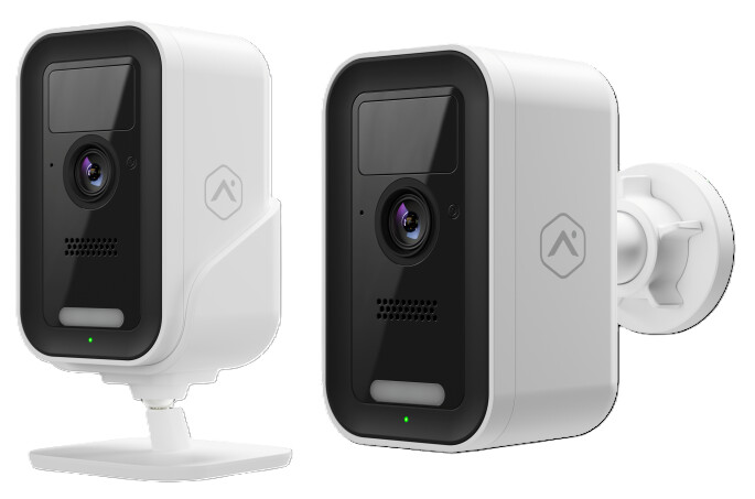
- ADC-V731B camera (included)
- ADC Universal Battery Pack (included)
- Wi-Fi (2.4 or 5 GHz) connection to broadband Internet (Cable, DSL, or Fiber Optic) Internet.
- A computer, tablet, or smartphone with Wi-Fi is required if the router does not have the Wi-Fi Protected Setup (WPS) feature
There are three options for connecting the ADC-V731B to the Wi-Fi network: Bluetooth (BLE) mode, Access Point (AP) mode or Wi-Fi Protected Setup (WPS) mode. BLE mode is the recommended method to connect the camera to the network, then AP mode if BLE mode is not. Some Internet Service Providers disable the WPS feature on customer routers.
In the box
- ADC-V731B camera
- ADC Universal Battery Pack
- USB-C Cable
- Installation card
- Wall mount
- Wall plate
- Wall anchors & screws (2)
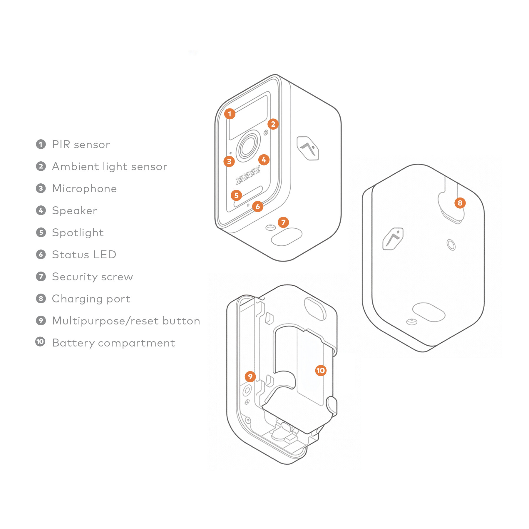
Overview
Pre-Installation
The following steps should be taken prior to the installation steps:
-
Unbox the unit. Carefully remove the device and all included components from the packaging.
-
To remove the battery pack:
a. Press the oval button located on the bottom of the device to release the housing.
b. Set the back housing aside and locate the black notch at the bottom of the battery pack.
c. Press the notch inward and slide the battery pack downward to remove it.
-
To reinsert the battery pack:
a. With the battery pack removed, carefully peel off any protective film covering the device or components.
b. Align the battery pack with the cradle and slide it back into place. Make sure you hear the notch click to confirm it is securely inserted.
-
Verify the LED indicator on the front of the device goes into pairing mode (blinking white).
a. When the device turns on, it begins blinking red to indicate the device is booting.
b. If the device is new or has not been previously associated with a network, the LED should begin blinking white to indicate it has entered pairing mode. If the LED is blinking white, replace the rear housing by pressing it together with the camera body, and proceed to the next section of the guide.
c. If the LED light does not blink white, press and hold the multi-purpose button located on the side of the device (accessible once the housing is removed) for 3 seconds, or until the LED begins blinking white. Once the LED starts blinking white, release the button and proceed to the next section of the guide.
Connect the camera to the Wi-Fi network
The ADC-V731B can be connected to the Wi-Fi network using BLE mode, AP mode, or WPS mode. BLE mode is the recommended method to connect the camera to the network.
BLE mode (recommended)
Important: BLE mode requires the ADC-V731B to be on hardware version 0401+ and firmware version 7.2.3+. The hardware version (HWV) and firmware version (FWV) are both printed on the label on the outside of the box. You can also find the hardware version printed on the camera underneath the battery.
To ensure a sufficient Wi-Fi signal, complete the following steps with the camera near its final location but prior to mounting.
- Connect the camera to power. Verify the device powers on and the LED begins to blink white.
- If it does not blink white after two minutes, press and hold the doorbell button and release when the LED begins to blink white (about 30 seconds).
- On a Bluetooth-enabled mobile device, log in to the Customer app or MobileTech app and complete the following step to add the video device to the customer’s account.
To connect devices via BLE mode using the Alarm.com app:
- Log in to the Customer app.
- Tap More.
- Tap Add Device.
- Tap Video.
- Scroll to find the device or use the Find Device search bar to enter the model number, and then tap to select the device to add.
- Enter a Device Name, then tap Next.
- Power on the device and verify the LED light is flashing white, then tap Next.
- If it is not flashing white, press and hold the button until the status LED starts blinking white. This may take several seconds.
- Tap Troubleshoot to learn more about how to get the device to that state.
- If Bluetooth is not enabled on your mobile device, approve the Bluetooth permission request when prompted, and then tap Next.
- Bring your mobile device close to the device being enrolled, then tap Scan.
- Allow time for your mobile device to scan for devices in the area.
- Select the device to set up. Verify the selected device’s MAC address matches the MAC address on the device being enrolled, then tap Connect.
- Keep your phone near the device while it connects.
- Once your phone is connected to the device, tap to select the Wi-Fi network. Either:
- Select a known network in My Wi-Fi Networks, or
- Select a new network in Other Networks, enter the password for the Wi-Fi network, and then tap Connect.
- Allow a few minutes for the device to connect to the network.
- Once the device connects to the Wi-Fi network, the device continues to complete the install on the customer’s account. Once the installation is complete, verify the video device works properly.
AP Mode
- Power on the camera. The camera’s LED will begin to blink white. If the LED is not white after two minutes, press and hold the WPS/Reset button and release when the LED begins to blink white (about 3 seconds).
- Connect to the camera’s Wi-Fi network. On an Internet-enabled device, connect to the Wi-Fi network ADC-V731B (XX:XX:XX) where XX:XX:XX is the last six characters of the ADC-V731B’s MAC address, which is located on the camera or on the packaging.
- Access the camera setup page. On the same device, open a web browser and enter http://v731binstall.com or 192.168.1.1 in the URL field. Follow the on-screen instructions to add the ADC-V731B to the Wi-Fi network. During this process, the LED will briefly turn red before blinking green. The LED will turn solid green once the connection is successfully completed.
- Once the LED is solid green, proceed to Enroll the camera to the account
WPS Mode
- Open the camera’s housing. Press the oval button located on the bottom of the device to release the housing.
- Enter WPS pairing mode. Press and hold the multi-purpose button located on the side of the device (accessible once the housing is removed) for 6 seconds, or until the LED begins blinking blue. Once the LED starts blinking blue, release the button to enter WPS mode.
- Activate WPS mode on the router. The camera will begin to connect to the Wi-Fi network. The LED will be solid green when the connection is complete.
- Once the LED is solid green, proceed to Enroll the camera to the account
Enroll the camera to the account
The camera can be enrolled to the Alarm.com account using the Alarm.com mobile app or website.
Alarm.com website
- Navigate to the Video Device Setup page by entering the following URL using a web browser: www.alarm.com/addcamera. The customer’s username and password for the account are required to log in.
- If the installation tutorial was used, it automatically navigates to this page after completing the tutorial.
- Enter the MAC address of the camera, then click Find.
- Enter a name for the camera, then click Install.
- Follow the on-screen instructions to finish adding the camera. An installation progress bar displays on the screen.
Alarm.com Mobile App
- Log in to the Customer app. The customer’s username and password for the account is required to log in.
- Tap Menu
- Tap Video Camera.
- Tap Enter MAC Address, then enter the camera’s MAC address.
- Tap Install for the camera on the Device Found page.
- Enter a device name, then tap Next.
- Follow the on-screen instructions to finish adding the camera. The installation progress displays on the screen.
Once the enrollment process is complete, move the camera to its final location. Prior to installing, verify the received signal strength at the installation location using the Alarm.com app. Once the signal strength has been verified, install the device with the included hardware.
Camera mounting overview
The V731B features standard ¼” tripod screw threading, allowing compatibility with a variety of mounting options. A wall plate and wall mount are included in the box for flush surface mounting. Alternatively, the camera can be placed directly on a flat surface or used with a variety of third-party mounts and stands. Follow the instructions below to mount the camera to a flush surface.
To install the ADC-V731B in its final location:
Consider recharging requirements when selecting the installation height. Make sure the person responsible for recharging can easily reach the camera and knows how to remove the battery pack.
-
Choose the mounting location. The camera should be mounted at least 8 feet above the ground on a flat surface (e.g., a wall or ceiling).
-
Verify there are no nearby obstructions that could interfere with the camera’s performance, particularly night vision.
-
Verify the location minimizes glare and avoids capturing unwanted motion (e.g., swaying trees or vehicle traffic), as this may negatively impact battery life.
-
Mark and drill mounting holes. Use the included mounting plate to mark the desired locations for the mounting screws.
- If mounting to drywall: Drill two 3/16” holes and insert the included wall anchors.
- If mounting to wood: Drill two 1/8” holes.
-
Attach the mounting plate. Align the camera’s mounting plate with the drilled holes. Use the included screws to securely fasten the plate to the mounting surface.

-
Secure the mount to the plate. Align the mount with the mounting plate following the printed instructions on the plate. Turn the mount until it clicks securely into place.

-
Attach the camera to the tripod screw.
a. Remove the optional small security screw from the packaging and insert it into the bottom of the camera to prevent the camera and back housing from separating.
b. Screw the camera onto the tripod screw threading until it is tight and securely fastened.
-
Adjust the camera angle. Loosen the collar on the mount to adjust the ball joint. Move the camera to point toward the area you want to monitor. Once the camera is positioned correctly, tighten the collar to secure it in place.
LED Guide
When operating on battery power, the status LED will light up in response to motion or when the camera’s state is altered (i.e., button press events, booting on, firmware upgrades, and deterrence responses).
General
| LED pattern | Description |
|---|---|
| Off | Power off or standby |
| Solid Green | Connected to Alarm.com |
| Blinking Green | Local network connection |
| Blinking Red | Power on, camera booting |
| Solid Red | No local or internet connection |
| Solid Blue | Low battery |
| Blinking White | Wi-Fi Access Point and Bluetooth Network Association modes (press and hold the button for 3-6 seconds) |
| Blinking Blue | WPS mode (press and hold button for 6-9 seconds) |
| Blinking Yellow | Power cycling (press and hold button for 9-12 seconds) |
| Blinking Red and Green | Reverting to factory default settings (press and hold the button for 12-15 seconds) |
| Blinking Green and Blue | Firmware updating |
In-Unit Charging
| LED pattern | Description |
|---|---|
| Blinking yellow and green | Charging |
| Blinking yellow and blue | Charging Failed |
| Solid green | Charged and connected to Alarm.com |
Battery Pack Charging
| LED pattern | Description |
|---|---|
| Solid Red | Charging |
| Blinking red and blue | Charging failed |
| Solid blue | Charged and connected to Alarm.com |
Troubleshooting
- If you have issues connecting the camera to the account, power cycle the camera and try again.
- If issues persist, reset the camera to factory defaults. Press and hold the WPS/Reset button until the LED is flashing green and red (about 12 seconds), then release the button. The camera will reboot to factory default.
If the camera was previously installed on a different Alarm.com account, it will need to be deleted before it can be installed again.
(Optional) Solar Panel Accessory for V731B Battery Camera (ADC-VACC-SP4W) installation
The ADC-V731B camera’s USB-C connection point is designed to be waterproof when used with the ADC-VACC-SP4W solar panel. When attached, the USB-C connector fits snugly against an internal gasket, blocking water from entering. This design has passed outdoor testing to ensure your camera remains safe and functional in any weather.