The PGP-IO9 is a PowerG two-way wireless transceiver that gives your alarm panel 2 hard-wired inputs (zones) and 2 hard-wired outputs (PGMs) or 4 hard-wired inputs(zones). It’s a great way to add wired sensors or control devices to a PowerG system without running wire all the way back to the panel.
Note: This guide is written for Qolsys IQ Panel 4 running firmware 4.6.1 or newer. For other panels, the enrollment menus may differ — consult your panel’s installer guide.
What You’ll Need
- PGP-IO9 device
- Small flathead screwdriver
- Long-nose pliers (for routing wires through the terminal block)
- Your sensor wire Max 10 meters (20–22 AWG recommended)
- EOL resistors if required (5.6k resistors included but can be calibratable from 2.5 k to 12 k)
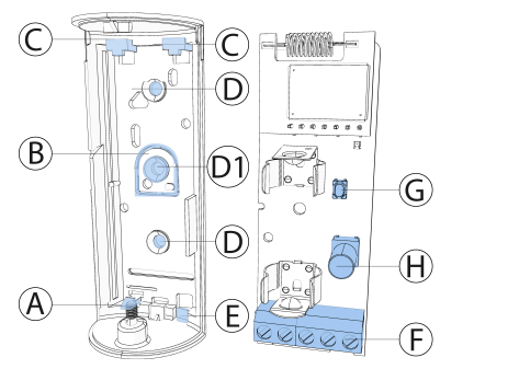
| Callout | Description |
|---|---|
| A | Flexible Electronic Board Retainer |
| B | Break-Away Segment |
| C | Electronic Board Edge Supports |
| D | Mounting Holes |
| D1 | Tamper Protection |
| E | Wiring Inlet |
| F | Terminal Block |
| G | Enroll Button |
| H | Tamper Switch |
Step 1 Configure Your Inputs (Optional)
The PGP-IO9 comes set up as 2 inputs + 2 outputs by default. If you need 4 inputs instead (and no outputs), you can convert it:
- Press and hold the enroll button until the red LED turns on, then release.
- If converted successfully to 4-input mode, the red LED flashes 3 times.
- The device is now ready to enroll as a 4-input device (use device ID 106-XXXX for 4 inputs).
Note: To revert back to 2-input / 2-output mode: press the enroll button until the red LED turns on, release, and the green LED will flash 3 times on success.
Step 2 Enroll the Device to Your Panel
- On the IQ Panel 4, go to Settings > Advanced Settings > Enter Code > Installation > Devices > Security Sensors > Auto Learn Sensor.
- Remove the battery pull-tab (or open and close the device cover) to trigger auto-enrollment. Alternatively, press the enroll button until the orange LED turns on.
- The panel should detect the device automatically.
- Optional manual enrollment: Select Add Sensor, then either:
- Scan the QR code on the device box using the IQ4 camera, or
- Manually enter the device ID printed on the label:
- 530-XXXX = 2 input / 2 output mode
- 106-XXXX = 4 input mode
- Select the desired zone number.
- Configure the zone parameters as needed (sensor type, loop, etc.).
- Select Done.
| LED Color | Signal Strength |
|---|---|
| Strong | |
| Good | |
| Poor — relocate the device | |
| No blinks | No communication — check enrollment |
Important: Poor signal is not acceptable. If you get a red LED, try a different mounting location and re-test until you get a green or yellow blink.
Note: After power-up or closing the cover, the device automatically enters Test Mode for 15 minutes — this is the best time to check signal strength.
Step 3 Choose a Location
Pick a mounting spot that meets these guidelines:
- Mount on a flat wall
- Keep it indoors, away from kitchens, laundry areas, bathrooms, basements, HVAC vents, or anywhere with high heat or moisture
- Avoid locations that are difficult to access — you’ll need to reach it for battery replacement and testing
- Stay within wireless range of your panel (run a signal test before finalizing the spot see Step 7)
Step 4 Open the Device and Remove the Battery
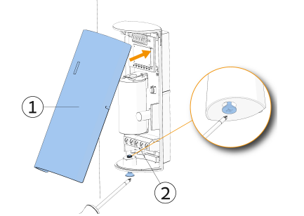
- Use a small flathead screwdriver to loosen the cover screw at the base of the device.
- Separate the cover from the base.
- Remove the battery (or pull the battery pull-tab to power it on if still installed).
- Flex the plastic retainer and slide out the electronic board so you can route wires through the wiring inlet.
Step 5 Mount the Base
- Position the device base at your chosen location.
- Screw the base firmly to the surface using the included mounting screws.
- Important: Make sure to fasten the break-away tamper segment to the wall frame. If someone tries to forcibly remove the device, this segment will break away and trigger a tamper alert.
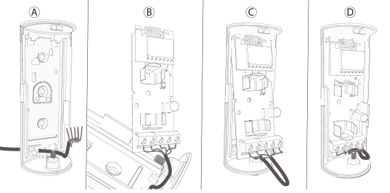
Step 6 Wire Your Inputs
The PGP-IO9 inputs support the following loop configurations (set in the panel):
| Configuration | How It Works |
|---|---|
| Normally Closed (NC) | Wire sensor contacts in series. Alarm triggers when loop opens. |
| Normally Open (NO) | Wire sensor contacts in parallel. Alarm triggers when loop closes. |
| End of Line (EOL) | Add a 5.6 kΩ resistor at the far end of the zone loop. Distinguishes alarm from tamper/short. |
| Double End of Line (DEOL) | Two 5.6 kΩ resistors for NC sensors — detects alarm, tamper, and short separately. |
Route your sensor wires through the wiring inlet at the base of the device and connect them to the terminal block
Note: Wire runs should use 20–22 AWG cable and be no longer than 10 meters from the unit to the sensor.
To calibrate the inputs after wiring:
- Make sure the device is enrolled and inputs are configured in the panel.
- Confirm all inputs are in their normal (secured) state.
- Press the enroll button until the green LED turns on, then release.
- If calibration succeeds, the green LED flashes 3 times. If the red LED flashes instead, return to step 1.
Step 6b Wire Your Outputs (if using PGM outputs)
The two PGM outputs can control devices with dry-contact inputs (sirens, lights, garage doors, relays, etc.). They support up to 15 VDC and can sink up to 1 A.
- Check your external device’s specs for its max voltage and current draw.
- Disconnect the battery before wiring.
- Connect the device wires to the output terminals (O1/O2) on the terminal block.
- Tighten the connector screws.
- Re-insert the battery.
Step 7 Reassemble and Test Signal Strength
- Reinstall the electronic board back into the plastic housing.
- Re-insert the battery.
- Clip the cover back onto the base and tighten the cover screw.
- After 2 seconds, the transmission LED will blink to indicate signal strength:
Step 8 Configure Device Parameters in the Panel
- In the panel, go to Installation > Devices > Security Sensors > Edit Sensor.
- Configure the following as needed:
| Option | Description |
|---|---|
| Sensor Input | Set loop type: Disabled, EOL, DEOL, NO, NC, or Global |
| Activation LED | Enable/disable the alarm LED indicator on the device |
Step 9 Associate Outputs with PGM Rules (if using outputs)
- In the panel menu, go to Settings > Advanced Settings > Installation > Devices > Security Sensors > PGM Output Rules.
- Find and select the device (by its ID).
- Select Edit PGM1 or PGM2.
- Select ADD and configure the rule parameters (what triggers the output and how).
- Define the location and save.
Battery Replacement
The PGP-IO9 uses a single 3V CR123A lithium battery (GP or Duracell). Expected battery life is approximately 3 years (2-input/2-output mode) or 5 years (4-input mode).
To replace:
- Loosen the cover screw and remove the cover.
- Remove the old battery.
- Insert the new battery, observing correct polarity.
- Press the battery down until it clicks into place.
- Replace the cover and tighten the screw.
Note: After restoring a low battery, allow up to 5 minutes for the panel to clear the low battery alert.
Troubleshooting
| Problem | What to Check |
|---|---|
| Device won’t enroll | Make sure panel firmware is 4.6.1+. Try opening/closing the cover again. |
| Poor or no signal | Relocate device to a different spot and re-run the signal test |
| Input not triggering | Verify wiring, loop type setting in panel, and that input calibration was successful |
| Low battery alert after replacement | Wait up to 5 minutes; alert should clear automatically |