I put the system in test mode yesterday. I still cant get either one of the glass break sensors to trip.
Does the fact that if I disconnect the piezo from the DW10, I get a sensor open status on the GC3 mean anything? Same if I tamper the DW10, I get a glass break sensor tamper message.
Does the fact that if I disconnect the piezo from the DW10, I get a sensor open status on the GC3 mean anything?
That would indicate that the sensor should be programmed correctly. As a normally closed circuit, opening it by disconnecting the wires should trip the sensor.
Is the glass you are testing laminated?
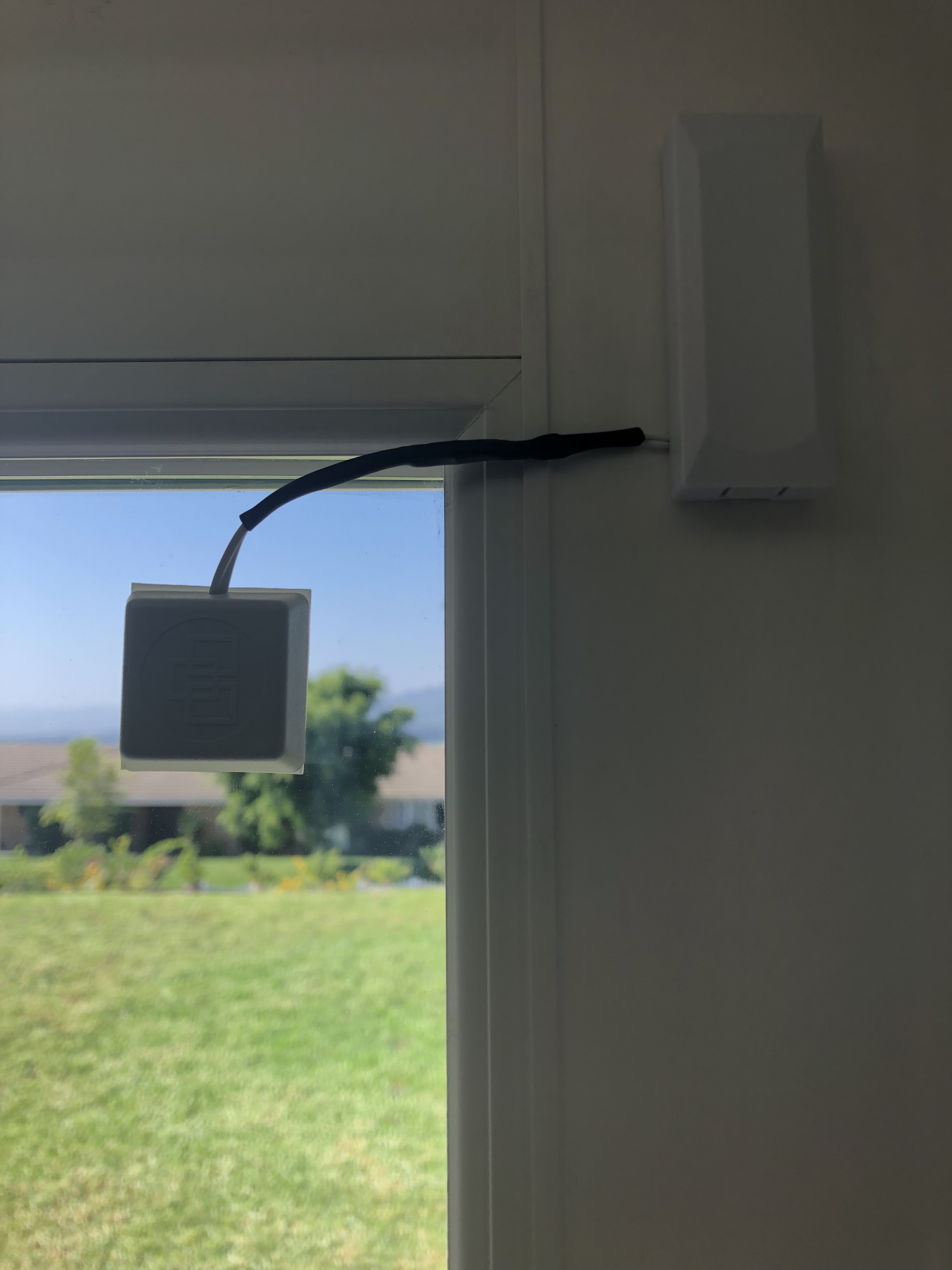
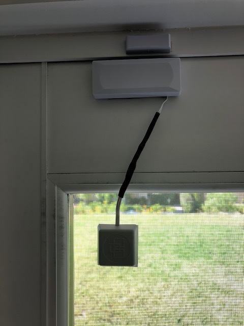
Can you post a photo of how you have the 5150 sensor installed on the window?
Just out of curiosity, how were the wires spliced? You mentioned you soldered them. Are the soldered leads individually wrapped with tape then taped together? If there is bare metal touching under the tape from one lead to the other then the circuit is shorted and cannot open unless you physically disconnect the wires from the sensor. I would check this first.
So I had sometime this past weekend to do some testing. This is what I found:
As mentioned by Jason on a previous post, the piezo is a normally closed sensor. When it is tripped it opens and triggers the alarm.
Both of the sensors I have, while disconnected can be triggered on the bench by a light tap. It was confirmed by checking continuity with a Fluke meter. This leads me to believe that it is not a wiring issue with the piezo.
If I then reconnect and then disconnect it to the DW10, I get an open message on the panel. This leads me again to believe that they are configured correctly.
The issue is when the piezo is connected to the DW10 it does not trip no matter how light or hard I tap or hit it (I actually broke one).
Yes, I can confirm there are no issues. If the wired shock sensors themselves function properly, there is no reason the sensor should not work aside from:
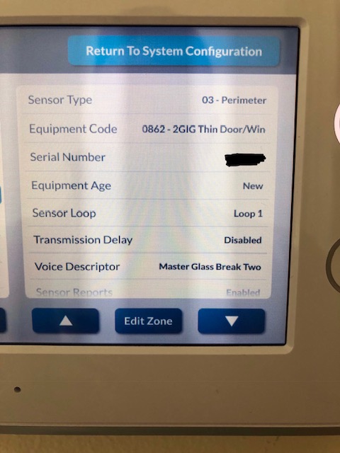
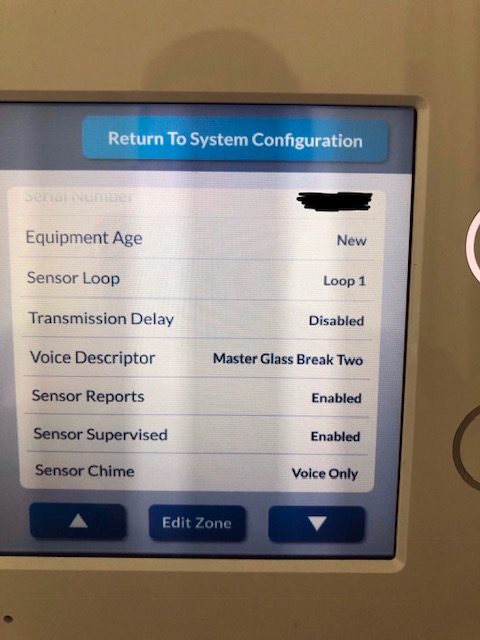
Programming issue
Wiring short/resistance
DW10 or 5150 sensor malfunction
What is the resistance value you see when the sensor is at rest and what does it jump to when triggered?
As far as sensitivity goes you can typically get one to go off by even just holding the shock sensor by the wire and flicking it with your fingernail. Does it work if it is done this way?
To test the DW10, just take a set of leads that plug into the DW10 and hold the exposed wires together, then pull them apart. Does the state of the zone change when you just close and open the circuit manually like that?
Is that at rest or when triggered? Please test both if possible.
Not sure what you mean. The connector to the DW10 is a plug.
Yes, but the other end of the plug wires are bare leads. They are what you soldered to the shock sensor.
Ultimately when troubleshooting you’ll want to isolate and test each possibility one at a time.
You said you had tested the 5150 to make sure they activated. You also said that unplugging the DW10 wired lead caused the DW10 to report open. The DW10 appears to be programmed correctly. These three things are good tests and indicate that they should absolutely function, unless the 5150’s wires were shorted or resistance was not sufficiently changing. We are using the same model products and same firmware panel to test successfully.
Do you have one of the 5150’s and DW10 lead wires that are not soldered together? Please test simply twisting the wires together instead of soldering, do not wrap them, just make sure that the two twisted conductor pairs do not touch each other. Then test the shock sensor. Does it report that way?
We may have solved the mistery. It looks like eventhough the wires were not shorted and the resistance value is basically the same (16 ohms closed with a max of 24 per manufacturer and over a mega ohm when tripped) with and without the soldered wires, somehow it’s interfering with the signal to the DW10. Can you recommend what size butt splice to use? For the last set I did, I used some 26-22 AWG but could not get them to crip tight enough for the small wire on the DW10 connector.
We actually used 26-22 awg. This was what we typically used, if I recall the fit of the DW10 and 5150 wire was rather snug. Needle nose pliers is all that is needed to crimp.
It should be the thin 3m double-sided tape included with the Shock Sensor. If you need to replace just match the thinness if possible. Any double-sided tape should be fine, but given you are looking for vibration, thicker outdoor tape may impact that.
Sorry to revive this thread again, but I still can’t get these guys to work. I did get the correct splices but with the same results as above. Event got a brand new piezo and dw10 and learned them into the GC3.
I can do an ohm check and see the piezo trip when I flick it with my finger.
Once learned, it will tamper if I remove the connector from the dw10, but can’t trip it.
Anything else I can try? A setting in the GC3 to check? (besides the sensor settings). This is pretty frustating at this point.
There is not a lot of variation and there are no additional settings which would need to be addressed.
One thing you might try is updating the firmware on the Control Panel, just to be certain that is not a possible cause of irregularity. The firmware version currently being run is a bit old at this point.
To remove all other possibilities and boil this down to the very basics:
Take one of the wired DW10 leads, disconnected from the 5150.
Twist the leads together. Does the Zone show closed on the panel?
Pull the leads apart. Does the Zone show open on the panel?
If you can open and close the zone by just opening and closing the leads of the DW10 wire, there is 100% no programming reason why the 5150 wouldn’t work the exact same way. That would mean that something in the installation of the 5150 is causing the problem, or possibly the original soldering damaged the 5150 due to heat.
What resistance change do you see when you test just the 5150 (when you flick it with your finger)?
According to the panel, it does not need a firmware update. Where/how can I download and update?
Your recommnended test worked as it should. I find it very difficult that ive somehow heat damaged 3x 5150s. The one im using to test right now, was never soldered and was crimpped. This 5150 reads 11.4 ohms when closed and open when flicked with my finger.