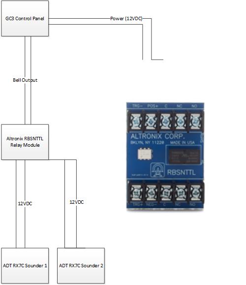
I have wired up the new GC3 control panel and “taken over” the existing wired zones in a Vista 20P panel. All is working well. I have two RX7C sounders that are already wired that I wish to use. I would like the Bell output on the GC3 to connect to the RBSNTTL relay. I have an external Paradox 12V power source that can be used to drive the sirens/sounders.
My question is which wires go where? I am assuming that the +/- trigger wires from the GC3 bell output go to the trigger +/- on the RBSNTTL. Then I am assuming that I can apply the 12V from the power supply to the respective leads on the RBSNTTL. Then would the red/+ wire from each sounder go to the common or to the NC or NO side of the relay? Same for the -/black wires?
Panel output goes to trigger. Take the Positive siren wire and connect to NO. Jump 12v input to common. Connect negative siren wire directly to negative. That should do it.
I’m interested in doing the same setup for two external sirens but am having trouble identifying the sounders + and - wires. I can easily identify the bell + and - coming out of my GC3e. Are there any recommendations on how to identify these wires?
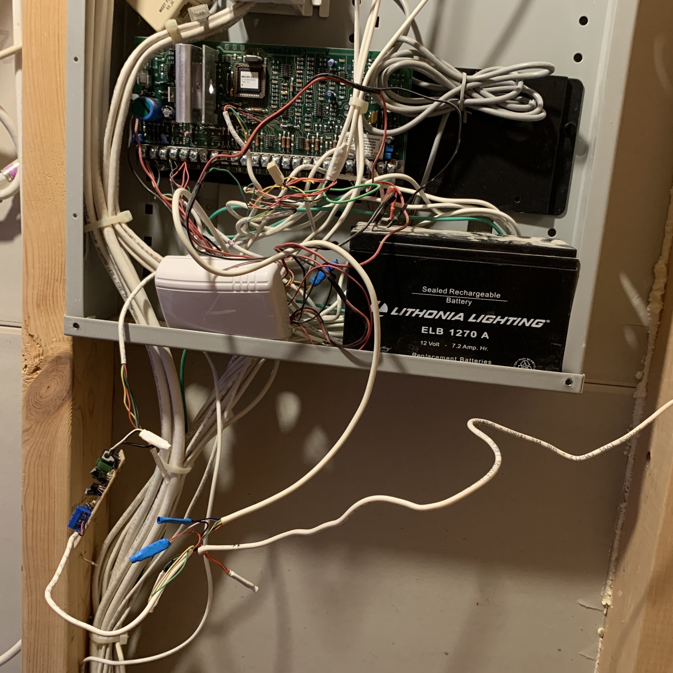
FWIW, the external sirens are sounding and are wired through an existing Ademco 20P board. I’m in the process of replacing all of the zones with encrypted wireless sensors and would like to eventually completely remove the hot mess of an install that Protection 1 did but would like to keep the external sirens in tact.
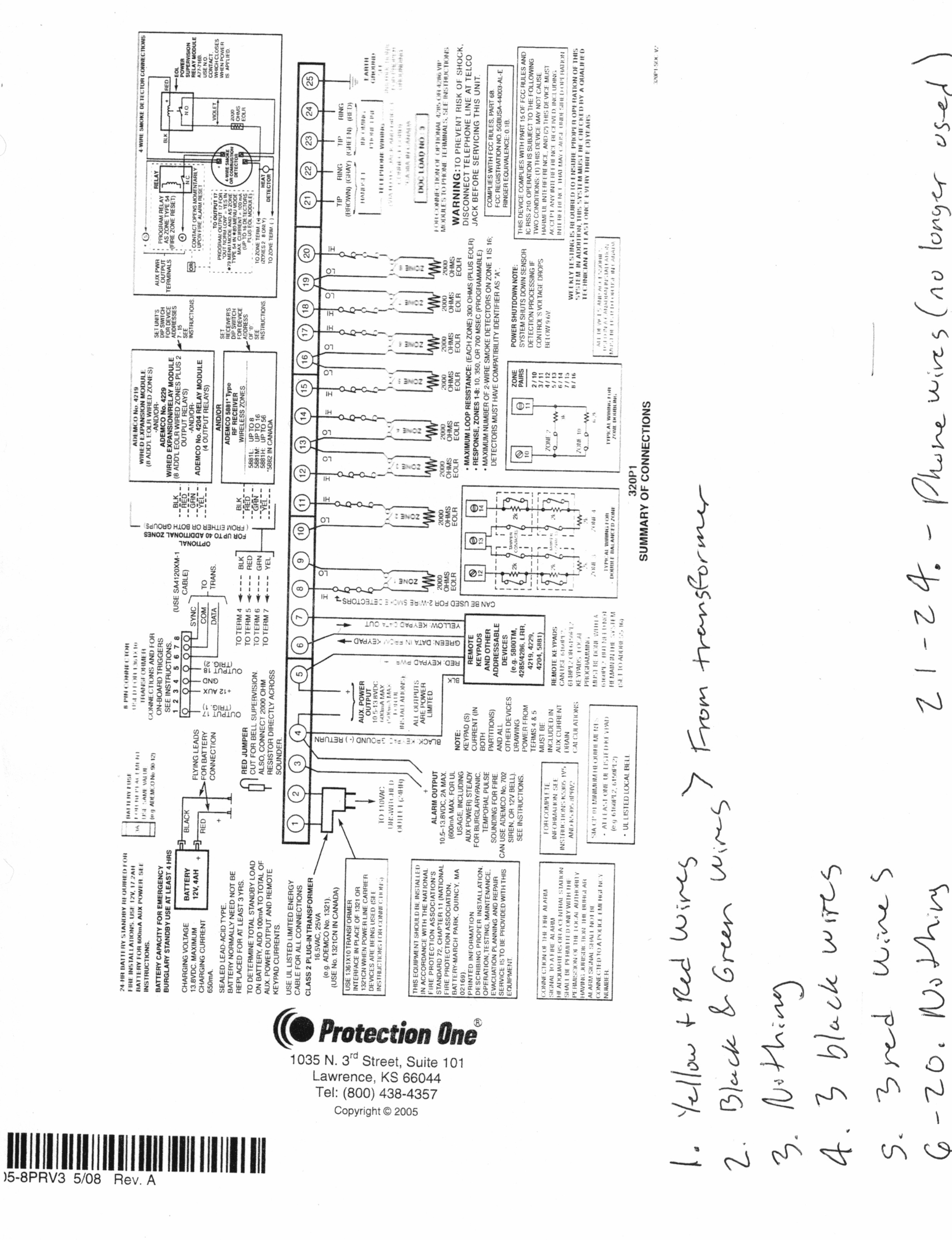
Picture of current situation is attached. From what I can tell the only terminals currently being used are 1 and 2 for power and 4 and 5 auxiliary power. 21-24 appear to be phone connections that are no longer being used. In the picture you can see the TAKE-345 (white box) but I have no idea what the little board is in the bottom left of the picture just hanging there by the wires. Is it safe to assume that 4 and 5 are powering the sirens and those are the leads I would need to connect to the RBSNTTL?
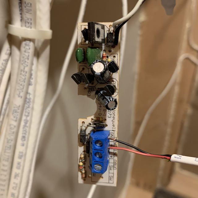
Still hard to make out, what does it say on the small white board under Honeywell.? The markings are obscured by the black capacitor, Its possible that the speakers run through that and are connected to the blue terminal block, but its hard to make out.
Awesome, that helps narrow it down. That bit appears to be the driver board from inside a siren , in this case possibly the Honeywell Wave 2.
Typically, this unit is inside the siren itself and the wires on the “left” side of the board (opposite the terminal block) would typically be soldered directly to the speaker like in the below video
I believe if you follow the wires connected to the black and grey wires on the driver, those should go to the speakers themselves.
The negative - from the bell output is in ground on the white board terminal block and the positive + from bell output is in terminal 2.