Brand new here. I have been slowly working my way through videos, forums, and other online resources in an effort to learn how to turn my current hard wired system into a 2GIG GC3 wireless alarm system with home automation. Pretty sure I am close to finalizing everything and purchasing my equipment. I have a couple last minute questions.
I have watch several videos on installing take over module. Looks pretty easy, but I also want to put the 2GIG GC3 where the old hardwired alarm panel is. From what I can tell, I should be able to power the 2GIG GC3 from the wires coming from the old box which should be behind the old alarm panel. What do I need to look for to make sure this can happen?
I want to use my current bell/audio device with the GC3 if this is possible. My alarm box is wired for Bell+ and Bell- I believe. My guess is these wires also go to the old panel. How can I find out if I can still use the old bell that came with the hardwired alarm? I know the GC3 has a place to wire the bell but I recall a video saying something about minimal power coming from the CG3.
I’m fairly new to this and I’m sure others will chime in, but, for what it’s worth…
18/2 wire will work to power the panel. More than likely the existing power wire can be used to power your new panel.
Make sure the bell you want to use draws no more than 120mA at 6-12VDC. I had to google my existing bell and it turned out mine wouldn’t work. You can pick up a zwave siren at lowes for around $30 that will work. If it must be wired then the Honeywell Wave2PD will work.
I have watch several videos on installing take over module. Looks pretty easy, but I also want to put the 2GIG GC3 where the old hardwired alarm panel is. From what I can tell, I should be able to power the 2GIG GC3 from the wires coming from the old box which should be behind the old alarm panel. What do I need to look for to make sure this can happen?
Yes, existing wiring will typically be sufficient to power your panel. However, just for clarity, you cannot power it using the old control panel can’s aux power output. You must power the GC3 using the included plug in transformer.
The wires can be removed from the old panel can and applied to the screw terminals on your GC3’s plug in power supplies.
You would want to determine the wire gauge. If it is 22 (exceedingly common for alarms) you may want to double up conductors if the length of the run is over 25 feet.
I want to use my current bell/audio device with the GC3 if this is possible. My alarm box is wired for Bell+ and Bell- I believe. My guess is these wires also go to the old panel. How can I find out if I can still use the old bell that came with the hardwired alarm? I know the GC3 has a place to wire the bell but I recall a video saying something about minimal power coming from the CG3.
Bell wiring in the old Alarm panel can would go directly to the siren, not the old keypad.
The circuit board in the metal can is the control panel, the keypad does not process/detect sensor alarms or send signals.
Make sure the bell you want to use draws no more than 120mA at 6-12VDC. I had to google my existing bell and it turned out mine wouldn’t work. You can pick up a zwave siren at lowes for around $30 that will work. If it must be wired then the Honeywell Wave2PD will work.
This is good advice regarding the bell. The GC3, like the GC2, has limited power draw available for wired piezos. Check the power specs of your current siren.
If it can be used, there are a couple options.
Is the siren nearby (often directly above) the keypad you will be replacing with the GC3 panel? This is somewhat common as it speeds up installation originally. If so it would be very easy to snag the wire to the siren and directly connect to the GC3.
If you do not need all 4 conductors for power for the GC3, you can use two of them to splice onto the siren wires at the old alarm panel can, and connect those two conductors to the GC3 bell terminals.
Thank you very much for this information. Your posts have generated a couple more questions.
What do you mean by “double up connectors”?
Beyond purchasing so 22 gauge wire, what is the easiest way to tell the gauge? Will it be written on it?
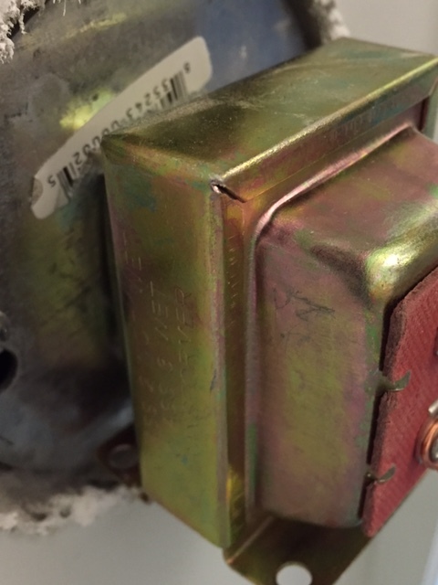
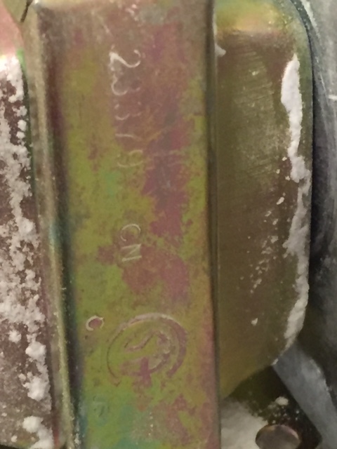
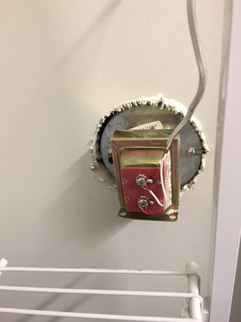
I was able to get a look at my bell. Just a small weird looking metal thing with wires connected to it. Tried to find some info on it so I could determine the requirements, cant even find a model number. Any hints here.
New issue. I thought my smoke alarms were wired together so when one went off they all went off. Was going to purchase the 2gig firefighter I think it is called to monitor all the smoke detectors. When I pushed the test button, only one went off. Should all of them go off when the test button is pushed or only when it actually alarms? Easy to solve I guess, just create a little smoke
Working through this. Thanks for all the help…It is greatly appreciated.
Old keypads will have four individual conductors in the cable. Four wires. To mitigate voltage drop over longer distances of cable you can connect two of the wires to positive and two to negative on the respective ends of the run. Effectively, this is using a larger gauge of cable.
2) Beyond purchasing so 22 gauge wire, what is the easiest way to tell the gauge? Will it be written on it?
You can find the gauge typically written on the sheathing. 22 AWG, 18 AWG, etc.
3) I was able to get a look at my bell. Just a small weird looking metal thing with wires connected to it. Tried to find some info on it so I could determine the requirements, cant even find a model number. Any hints here.
Happy to take a look. Can you post a photo? Try to get any stickers/writing.
4) New issue. I thought my smoke alarms were wired together so when one went off they all went off. Was going to purchase the 2gig firefighter I think it is called to monitor all the smoke detectors. When I pushed the test button, only one went off. Should all of them go off when the test button is pushed or only when it actually alarms? Easy to solve I guess, just create a little smoke
Are these low voltage smoke detectors from an old alarm panel? or are they house voltage interconnected detectors?
My alarm pad only needs 3 wires Data/Com/Pos so I thought I may be out of luck. Didn’t even think about the possibility of a 4th unused wire. THANKS!!!
It is a brand new house. I was told they were interconnected but once we took possession I had just a minute to test and pushed several of the test buttons. They only “alarmed” at the individual smoke detector when the test button was pushed. Tonight I plan on unhooking them from the ceiling to see if they even have power wires.
Also, picture of the alarm when I get home tonight.
Also I just thought of something. If I am using the 2GIG takeover module, it will be powered off the existing board’s transformer and the panel wires will be removed from the exiting board and plugged into the GC3 transformer, effectively now needing two power supplies. Is this correct?
Also, just went to order and the GC3 is not in stock. Do you know when it will be back in stock? Can I order the GC3 from elsewhere and get everything else including the cellular module from you guys?
Also, just went to order and the GC3 is not in stock. Do you know when it will be back in stock? Can I order the GC3 from elsewhere and get everything else including the cellular module from you guys?
You can, but we did have one more. Product updated.
Compatible equipment can be purchased anywhere and used with our service.
If I am using the 2GIG takeover module, it will be powered off the existing board’s transformer and the panel wires will be removed from the exiting board and plugged into the GC3 transformer, effectively now needing two power supplies.
Yes, two would be needed. The Take is powered off of the old board’s 12V DC aux power output though, not the transformer directly. But yes, both transformers would ultimately be plugged in and necessary in that circumstance.
The Take also uses the old panel board for battery backup circuit.
We have both Verizon and AT&T phones. My wife said her AT&T phone was only 2 bars out of 5 at our current panel. I am unable to test my Verizon phone because I am still at work. If Verizon is worse can I exchange or can I post Verizon results here tonight before shipping?
AWESOME SITE BY THE WAY and THANKS FOR ALL YOUR HELP!!!
Thank you for the bell information. Is there any harm in wiring the bell to see if it works? Or could this damage the 2GIG GC3?
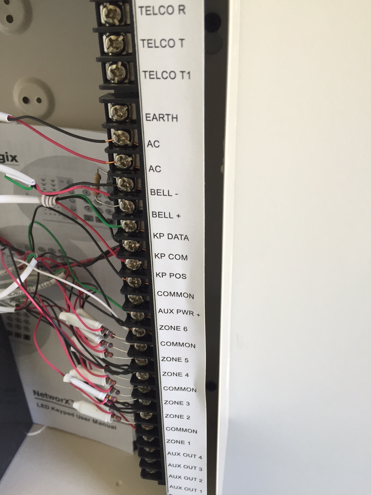
Also, any way to open/activate a zone to see which wire in the can corresponds to which zone on my old panel? I have a total of 11 zones. Zone 6 I believe is a powered CO/Smoke. Zones 1-5 in the can each have two wires going to them. The panel zones 1-5 need to correlate to two each zones on the panel. I would assume zone 1 in the can are zone 1 and 7 on the panel, zone 2 in the can are 2 and 8 on the panel as so on and so on but I am not sure. Besides, I still need to iron out which wire in the can is say zone 1 and which is zone 7.
Zone 6 seems to be the Carbon Monoxide/Smoke. The installer hand wrote CO for zone 6. I understand that the zone will still be powered by the old panel but the new GC3 will not be able to sense an alert and react to it. Correct? My plan is to ultimately figure out what activates what and find the best loction for a 2GIG firefighter. Any better ideas?
Is there any harm in wiring the bell to see if it works? Or could this damage the 2GIG GC3?
Anything you are unsure about, I would not connect. That image looks to be a door bell transformer, not a siren.
Typically your old system would have a piezo siren somewhere. Sometimes installers will be…(what’s a nice word for lazy?) and the siren might be located right near the old panel can.
Also, any way to open/activate a zone to see which wire in the can corresponds to which zone on my old panel?
Do your current system’s keypads still function? If so you should be able to open a sensor, and view the open zone number on the keypad. This is typically easiest.
The most surefire method is to use a multimeter to detect resistance on the circuits. Remove a pair of corresponding zone/common wires from the board. Attach the multimeter leads to them. With all sensors closed you should show low resistance. Then, open one sensor at a time to determine which opens the circuit and shows “infinite” resistance. Essentially what the multimeter would read if you held to two leads away from one another not touching anything.
I understand that the zone will still be powered by the old panel but the new GC3 will not be able to sense an alert and react to it. Correct? My plan is to ultimately figure out what activates what and find the best loction for a 2GIG firefighter. Any better ideas?
A firefighter will only trip from a smoke detector alarm cadence. CO detectors do not produce the same alarm sound.
Do all of your smoke detectors produce a local alarm? Some models do not have a local sounder and rely on the panel siren.
Keep in mind the GC3 does have a hardwired Smoke detector zone, however it is not currently enabled, pending firmware.
If the existing panel is plugged into the battery and the take module gets power from the existing panel, do you still plug the take modules battery leads into the battery?
If the existing panel is plugged into the battery and the take module gets power from the existing panel, do you still plug the take modules battery leads into the battery?
Yes. Back-up battery power must come from the battery leads on the TAKE.
Both the TAKE and the old Panel should be connected to battery
Awesome. I got my system up and running this weekend. Knock on wood, no issues and everything went smooth. The last two things I have to deal with are the smoke/carbon monoxide zone. It is a powered zone (I think that is what it is called) as it has more than a high and low wire. It has two wires that plug into aux power. No way to add this the the takeover module?
I also have to deal with my bell. I need to do some research on that though.
The last two things I have to deal with are the smoke/carbon monoxide zone. It is a powered zone (I think that is what it is called) as it has more than a high and low wire. It has two wires that plug into aux power. No way to add this the the takeover module?
No, Smoke detectors/carbons unfortunately cannot be used through the TAKE-345. It is not UL listed to do so, and it only functions with NC (normally closed) sensors, smokes are normally open.