Confirm Panel Compatibility
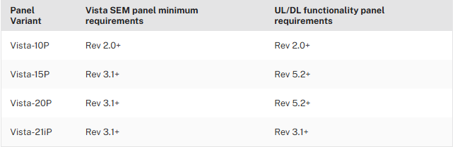
The SEM is compatible with the Honeywell/ADEMCO VISTA 10P, 15P, 20P, and 21iP panels. Panels or PROM chips should work as long as they were manufactured in 2005 or later and have the following Rev requirements:
UL/DL considerations:
- If the UL/DL compatible SEM is connected to a Vista-15P or 20P panel lower than revision 5.2, the panel functions the same as a legacy SEM, with the exception of being able to communicate over broadband.
- To get all of the enhanced functionality (such as access to uploader/downloader settings), the Vista panel must meet the minimum revision number as shown in the UL/DL functionality panel requirements column above.
Verify the panel has sensors programmed
Verify the panel has all sensors programmed properly. For more information about programming sensors via the panel’s keypad, contact the panel manufacturer.
Test all sensors to ensure the keypad displays sensors properly (e.g., open/close contact sensors, walk in front of motion detectors, etc.).
Verify incompatible devices are not attached
If any of the following devices are attached, remove the device before using the System Enhancement Module (SEM) with the Honeywell/ADEMCO Vista. Having any of these devices may result in unexpected behavior from the security panel. If any of these devices are present, power down the system, remove the device(s), and power on the system. The SEM will attempt to scan after it powers on.
- AVS devices
- This device is used for Two-Way Voice, which is not available on the SEM. The AVS also allows zone descriptors to be announced.
- 4232CBM (Connected Building Module)
- Telephone (POTS) line
- The SEM should be the only communication path for alarm signaling to the monitoring station.
- 2GIG-STZ-1 thermostat
Sensor Activity Monitoring (SAM) is not compatible with the following device. Turn off SAM for this sensor, if installed.
- 5822T Tilt Sensor
Note : Sensors programmed with zone doubling can interfere with Sensor Activity Monitoring (SAM). It is not recommended to use zone doubling on the SEM-Honeywell/ADEMCO Vista.
Enter Programming
- Enter the installer code.
- Press [800].
- Press [*].
- The SEM should take over and execute the initialization scan within 1 minute.
- If the scan didn’t start after a minute, press *99 to exit.
Change the installer code
- Enter the current installer code.
- Press [800] to enter programming.
- Press [*] to enter a field.
- Press [20] to program the new installer code.
- Enter the new code to be the installer code.
- Press *99 to to exit.
- After exiting programming mode, the keypads should display MODEM COMM or CC for about 5 seconds to indicate sync on a UL/DL compatible SEM.
Set programming necessary for sync
- Enter the current installer code.
- Press [800] to enter programming.
- Press [*] to enter a field.
- Ensure the following programming changes are completed:
- *29 (IP/GSM) set to 1
- *43 (Primary Account No) set to 1111
- *48 (Report Format) set to 7,7
- *196 (SEM’s keypad address) set to 1,0
- Press *[96] to reset the account number and initialize the downloader.
- Reinitializes the panel’s download ID and subscriber account number.
- Press *[99] to exit.
- After exiting programming mode, the keypads should display MODEM COMM or CC for about 5 seconds to indicate sync on a UL/DL compatible SEM.
Perform Communication Test
Like any Alarm.com-integrated system, sending a communication test from the Honeywell/ADEMCO Vista panel is necessary to initialize communication with Alarm.com or verify the module is communicating on the cellular network.
To send a cellular communication test using the keypad:
- Press [#].
- Press [987].
- Press [*]. This sends a cellular communication test.
Upon completion, there is no local indication of success or failure.
Broadband communication test
Using a Dual-Path SEM-Honeywell/ADEMCO Vista, a broadband communication test can be sent using the keypad.
To send a broadband communication test using the keypad:
- Press [#].
- Press [963].
- Press [*]. This sends a broadband communication test.
Upon completion, there is no local indication of success or failure.
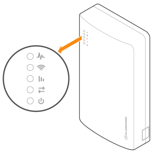
LEDS for SEM 300
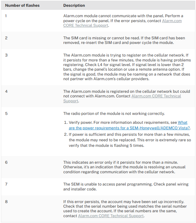
L1 flashes when an error is encountered. The number of flashes indicates the error number. If there are two or more errors at the same time, the errors flashes one after the other. The LED stays off for at least four seconds between errors.
Note : It may take up to 10 minutes before L1 detects and flashes an error code.
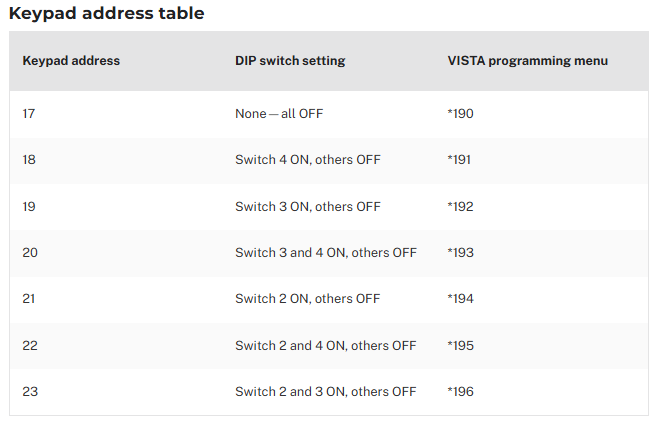
Change the SEM’s Keypad address
-
Identify an available keypad address.
-
Enable the address at the keypad by entering the corresponding programming command using the Keypad address table.
-
Power the system off.
-
Adjust the SEM DIP switches on the SEM to match the corresponding keypad address using the Keypad address table.
-
Power the system on. Verify a zone scan initiates upon power up.
Verify bus devices and power budget
For Honeywell/ADEMCO Vista panels, the maximum combined current of connected devices should not exceed 600 mA. Connect additional devices to an external power supply if more power is needed.
- Make a list of all bus devices attached
- Verify that the power budget meets the requirements using the Power Budget Calculator.
- If the bus device configuration needs to be changed, power down the system before removing devices.
- If it makes sense, pare down to the SEM and a single alphanumeric keypad.