Can I use the 1361-GT transformer, that has 2 A/C and a single ground to power BOTH the Vista 20P and a 2GIG Sp1 Control panel off of that single transformer?
Also, I am upgrading my alarm system, is the Vista 20P the best board to use with the G3CE if money is no issue?
Can I use the 1361-GT transformer, that has 2 A/C and a single ground to power BOTH the Vista 20P and a 2GIG Sp1 Control panel off of that single transformer?
No. The 2GIG SP1 uses a 14 VDC transformer. Connecting it to an AC transformer would result in damage to the SP1.
Always be sure to use the power supply that comes with the panel.
Also, I am upgrading my alarm system, is the Vista 20P the best board to use with the G3CE if money is no issue?
Do you already have a Vista system in place or are you talking about adding one?
The 2GIG GC3e is the control board, not just keypad. It houses the Alarm.com cellular communicator and main logic board. The Vista panel wouldn’t be used with it.
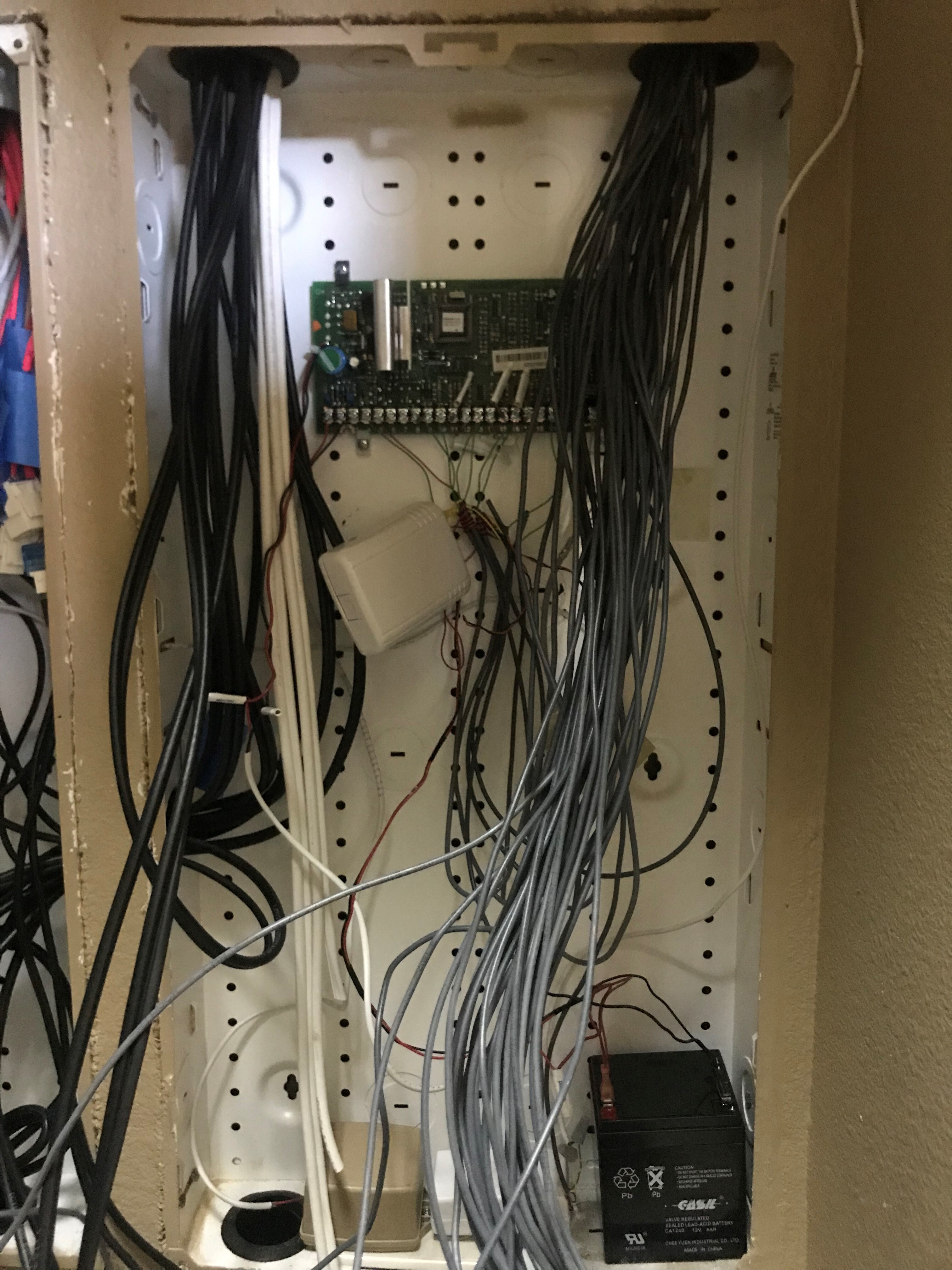
The way my alarm is set up is everything goes into a master control panel, inside a closet and then to a 20P, to a take over module and then my control panel has a single wire that goes into my laundry room into the main control room. I would have to use the 20P for a set up like that wouldn’t i?
I’m just upgrading the entire system. It has an old 2GIG GC2 panel, that only has 8 zones hooked up. I’m finishing the alarm set up. It’s all hardwired, I have to finish hooking it all up. I have 36 zones I have to finish installing.
So Far I have purchased the 2GIG GC3E, I am adding a SP1 in my room. I was just curious if the 20P panel was worth upgrading.
All the Gray wires on the right are zones I have to add to my system. As you can see I only have 8 hooked up. I still have 20+ I need to add into the system. Its been like this for 10 years. It’s time to finish it!
Ah, yes I just wanted to make sure you weren’t buying a Vista along with the GC3e.
Technically the old Vista panel is only there in this setup to provide a battery backup charging circuit and aux power to things like motion detectors and glass break detectors. It could be replaced by something like the AL624.
If it is already in place though, it is much easier to just use the Vista board though, of course!
The only reason to really swap out the Vista for something like the AL624 is that the AL624 can provide twice as much current at 12VDC.
The Vista supports up to 600ma.
Each TAKE-345 is 50ma. If you are using just four TAKE-345s and a dozen powered sensors or so, you should come in under 600ma. (door contacts are not powered)
Based on the image, just a quick suggestion: make sure that any 2GIG TAKE-345 takeover modules are not placed inside of a metal housing, as this can greatly weaken the wireless signal they send to the panel.
The GC3e and the SP1 should be powered by their included 14VDC transformers individually.
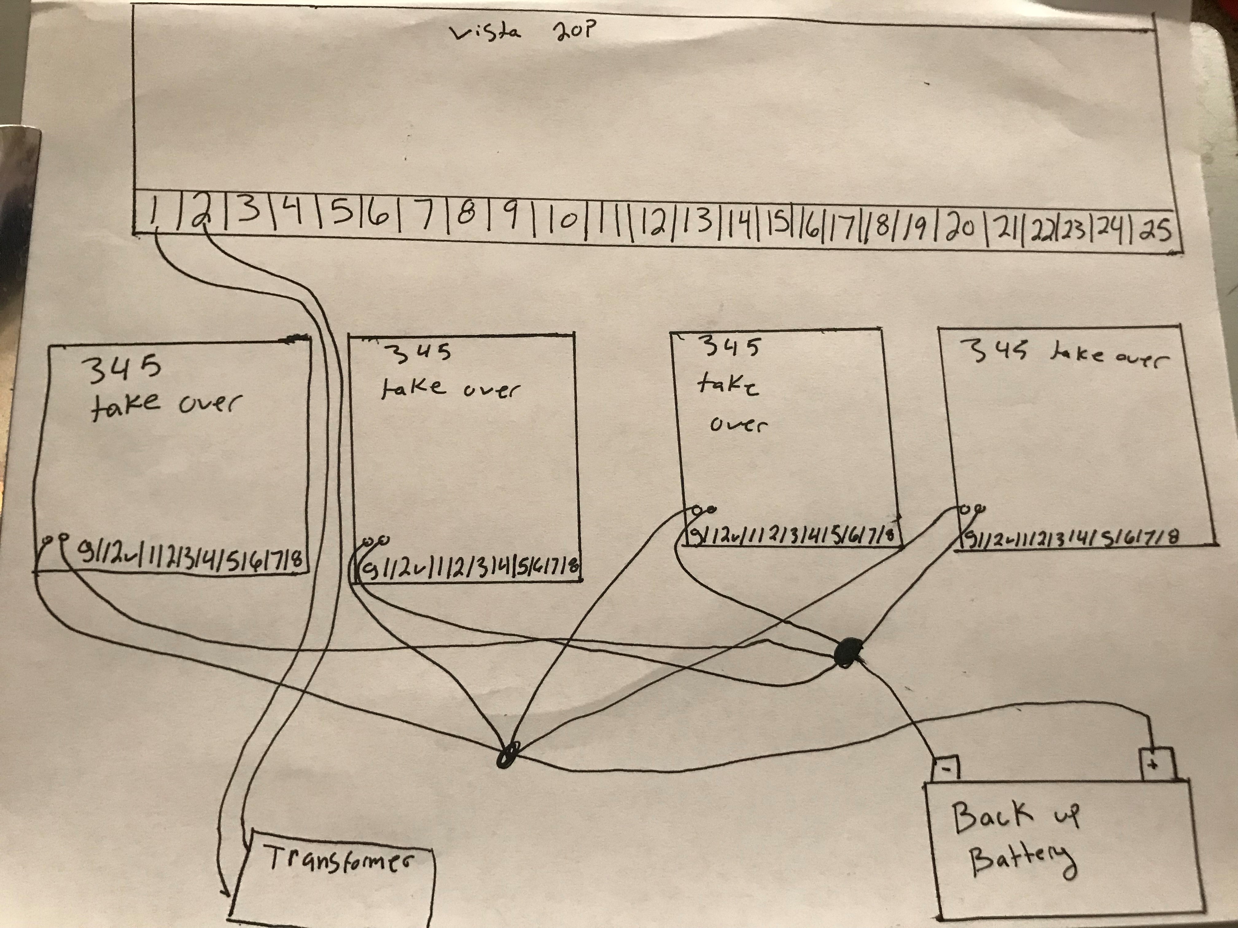
Okay, I drew up a diagram so far and I have a few questions. I am trying to wire this as clean and professional as possibly.
So, for the back up battery on the Take over 345 modules, I drew in the diagram that I’ll just combine all of them and run a single wire from the wire nut to the back up battery. I will do that for the negative and positive to the back up battery. Would that be correct?
Now on the Vista panel. Number 1/2 go to the transformer to power up the panel.
On the 4 Take over modules, I would just run all of the wires to a wire nut, and run a single wire out of the wire nut
So On the take over modules, the Ground and the 12V Would run to what number on the take over module? Would I run the Ground from all the take over modules to number 4, and run the 12V to number 5 on the vista panel?
I will ask you another question once you answer this one, So I’m not getting ahead of myself.
So, for the back up battery on the Take over 345 modules, I drew in the diagram that I’ll just combine all of them and run a single wire from the wire nut to the back up battery. I will do that for the negative and positive to the back up battery. Would that be correct?
I wouldn’t recommend this. I wouldn’t cut into the battery wires of the TAKE-345 units. The battery connectors for the TAKE-345 already have a coupler tab to attach another battery connector. Multiple takeover modules can be attached in this manner.
So On the take over modules, the Ground and the 12V Would run to what number on the take over module? Would I run the Ground from all the take over modules to number 4, and run the 12V to number 5 on the vista panel?
There are G and 12V inputs labeled on the Takeover module. Each takeover module would have these wired to GND - and AUX + power respectively (which would be terminals 4 and 5 on the Vista).
Thank you for helping, I’ll ask you a few more questions if you dont mind. I would rather ask them in separate replies to make things easier so nothing gets missed.
Do you think it would be “cleaner” or more professional just to pull 4 wires to the nut on the 20P board, or to wire nut them and throw one a single lead back to the panel? For a 3rd option, would it be better just to daisy chain them all to the last one, and pull it from the last one on the chain to the 20P?
So this is where I get confused. I have 4 wirings coming from all of my doors/window contacts. I obviously only need to use 2. All the zones I am adding are just windows/doors
So this is what the Vivint did when they installed it from the previous owner. They pulled the Yellow wire and used it in the 1-8 Slots in the take over module. Then they used the green to 20P board.
I understand that All the yellows will go to the take over modules in the slots I need them (1-8). But where the heck do I put the other wire to? The Green wire. Which number on the 20P do they all go? Do they go on the LOW or high Side on the 20P? Do i have to keep the resistor in there or not?
Do you think it would be “cleaner” or more professional just to pull 4 wires to the nut on the 20P board, or to wire nut them and throw one a single lead back to the panel? For a 3rd option, would it be better just to daisy chain them all to the last one, and pull it from the last one on the chain to the 20P?
For ease of troubleshooting and identifying issues, I would always run wires directly from each TAKE to the terminals on the Vista board, unless there are simply too many of them.
I understand that All the yellows will go to the take over modules in the slots I need them (1-8). But where the heck do I put the other wire to? The Green wire. Which number on the 20P do they all go? Do they go on the LOW or high Side on the 20P? Do i have to keep the resistor in there or not?
A zone circuit uses a zone terminal and a gnd terminal. The “LOW” terminals are GND terminals on the Vista board.
All the GNDs are connected internally, and all that needs to happen with the green sensor circuit wire for each zone is to connect to G on the TAKE-345 its corresponding yellow wire is connected to.
All the GNDs/LOW/G are connected, so each green wire just needs to be connected to one of them somehow.
With more than one TAKE-345 it can get pretty crowded at the alarm panel terminals, so this is where I would wire nut them together and connect them to a GND/LOW terminal.
It would be best to wire nut all the Green wires for one TAKE-345 and select a LOW terminal to connect it to. That’ll let you efficiently label the bundle and keep it neat. Hopefully that makes sense. Let me know if it would be better as a diagram!
The TAKE-345 is looking for any resistance value under 3Kohm I believe. You wouldn’t need the resistors in place.
I am getting my new panel in a few days, once I am ready to install the new GC3E with the new Antenna. Do i just message you and ask you to add that antenna or do i do a cell test with it and it’ll automatically change on my alarm.com? I would also want you (if you can) to just completely delete all the zones on my account, as i would be completely removing and rewiring all of the zones.
If you are swapping the cellular module on an existing Surety service plan, you can actually do that at any time through your Surety System Manager here. You will just need the IMEI from the new module.
After performing the swap, you will be instructed to run a cell phone test on the new panel to get it connected.
Alarm.com will automatically pull the new panel’s zone list and overwrite the one from your previous panel. If you already have the sensors installed they will populate on your account. If you learn the sensors in afterward they will populate as you add them.