I’m down to the last step in setting up my IQ Panel 4 – connecting the included transformer/barrel connector wire to the pre-existing wiring – and just want to make sure I do it right.
First of all, would it make sense to get a spare barrel connector wire in case this doesn’t work? Do you know if that can be ordered separately (or is it a generic part?) or if I would need to buy a spare transformer too?
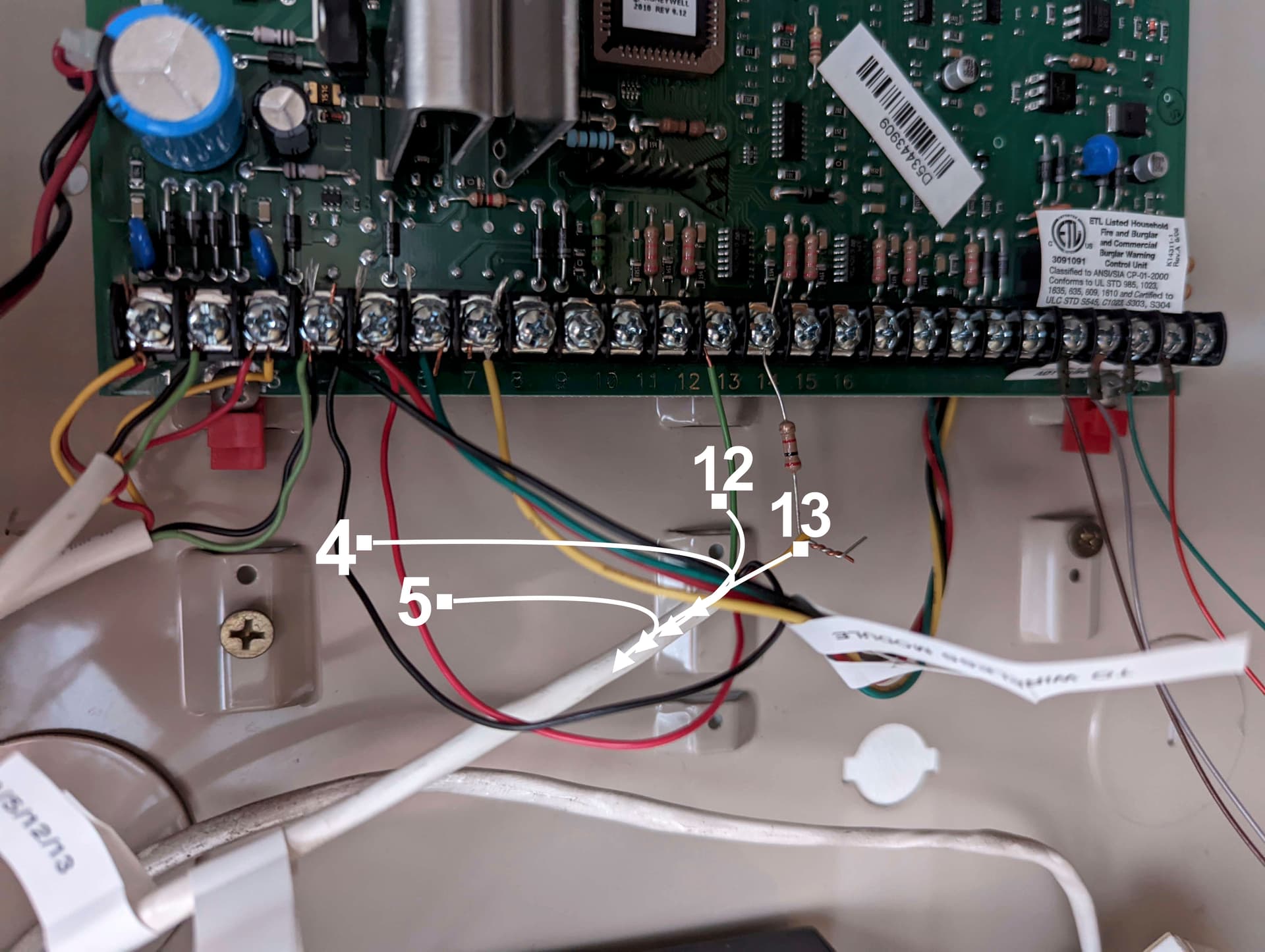
This is the wiring coming from the panel. I’m assuming these four wires are what connected to the old original ADT keypad that I removed.
If that’s the case I would just disconnect them from the circuit board, double them up and splice to the transformer wire? And remove the resistor?
There is also a separate black wire only that was connected to the #4 terminal on the circuit board. It goes into the wall in a way that would lead straight to the keypad, whereas these four wires seem to go up into the ceiling, but could then come down and out to the keypad, just more indirectly.
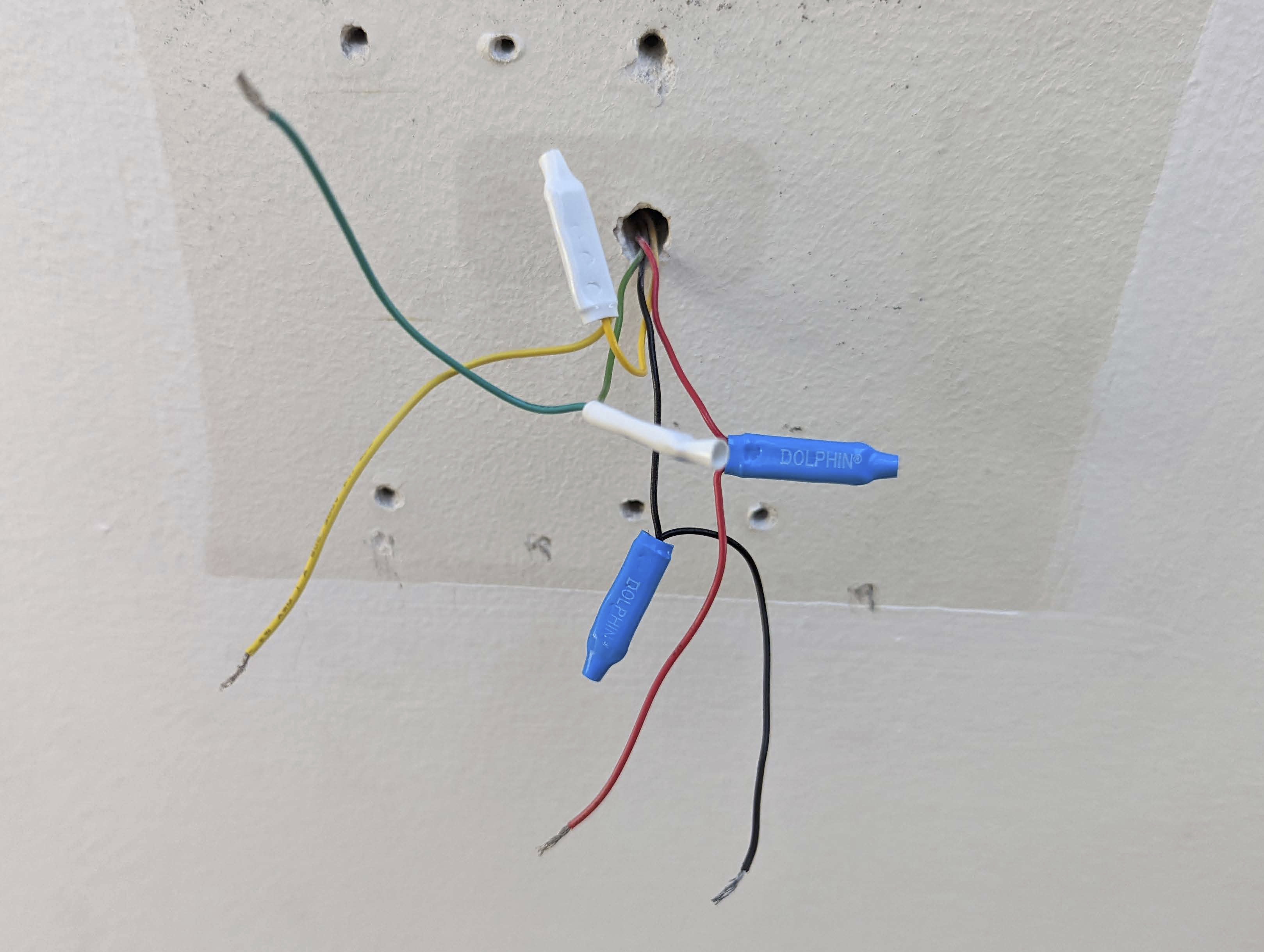
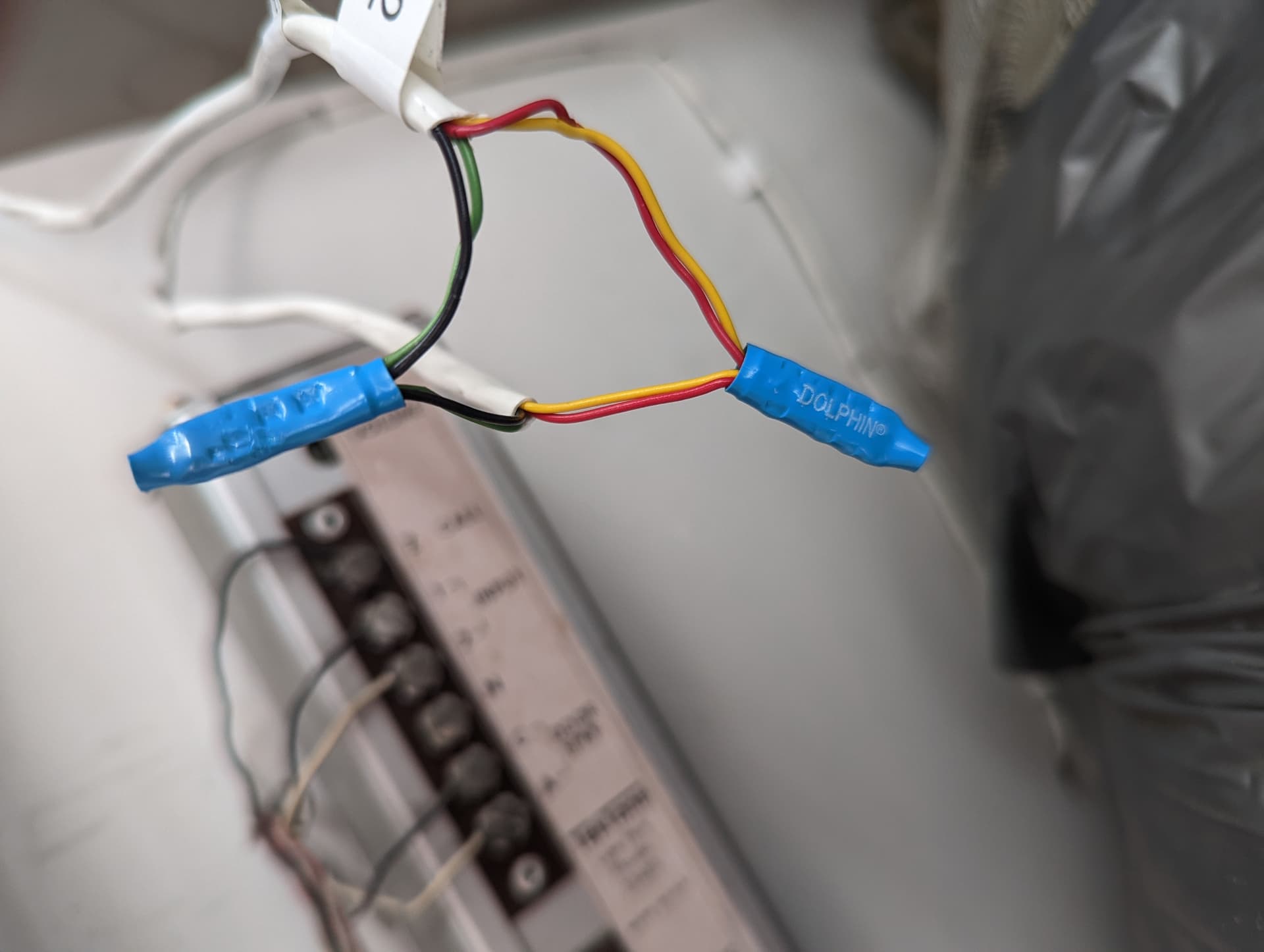
Here are the wires that were connected to the keypad. Any idea why the Dolphin connectors? Can they be removed? The total distance to the panel would be short even if the wires went up into the ceiling first. Less than 50 feet for sure. But is it preferred to double up the wires anyway?
Finally, I was going to make the splice with some new Dolphin connectors – is that an effective way to make the splice from the 7V transformer wire to the old wiring?
If that’s the case I would just disconnect them from the circuit board, double them up and splice to the transformer wire? And remove the resistor?
No. A keypad wire will not have a resistor. That is likely a zone circuit. Look at the wiring diagram for that panel.
The keypad wires are going to be the ones in terminals 4, 5, 6, 7.
Here are the wires that were connected to the keypad. Any idea why the Dolphin connectors? Can they be removed? The total distance to the panel would be short even if the wires went up into the ceiling first. Less than 50 feet for sure. But is it preferred to double up the wires anyway?
They’ve just pre-run the wire through a small hole, then spliced on behind the keypad. No functional reason to keep the connectors that way when you replace, go ahead and remove them.
Yes, you will need to double the conductors.
Finally, I was going to make the splice with some new Dolphin connectors – is that an effective way to make the splice from the 7V transformer wire to the old wiring?
Yes, I usually recommend the conductive gel filled kind because it helps avoid corrosion and maintain good contact long term. But any B-wire connector is fine.
That must be it. But you can see only the black wire was connected. These four wires are what go into the wall in a way that would seem to go straight to the keypad.
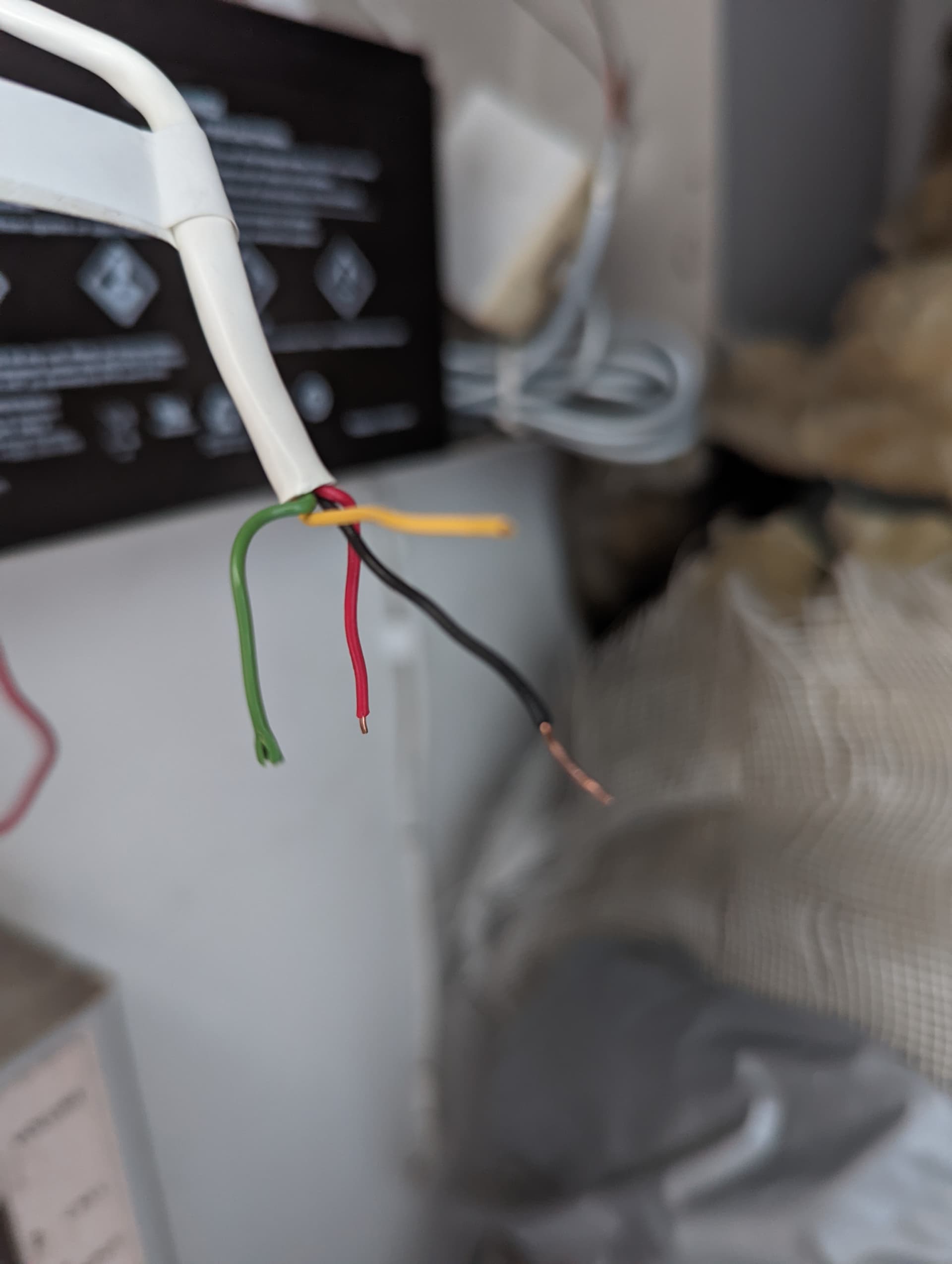
Is it possible that the keypad was connected only to the black wire on #4? Is it possible the red, yellow and green wires were connected to the panel even though they aren’t stripped?
I’m confused now because that’s literally all there is. If it isn’t the 4,5,12,13 wires, the only other wires go to the wireless module or are the wire with the just the black connected to #4…
But the keypad was definitely working before I removed it.
If the 4 wire cable that has no white jacket on it running down behind the circuit board runs to a wireless module than the only thing that makes sense as the keypad wire is the other 4 wire in a white jacket in the last picture you posted. No other combo of wires as shown in any of your pictures would be correct for the keypad.
The keypad can’t work with only black connected, it would have no power. If it had only black and red connected to 4/5 then the keypad would have power but no data to the panel to actually control it.
Could 4/5/12/13 been run to the keypad? Sure it could have. In that scenario the keypad would have power but not be able to actually arm/disarm the system as the data wires would not be going to the right terminal.
So when you say the keypad was “working”, does that mean you could actually arm/disarm the system or did it just have power and make beeps but not actually do anything? Also, what’s the actual model number of the keypad?
Do you have a volt meter? If so, connect a pair of wires to a AA, AAA, or 9V battery and check voltages on the other end to see if you have juice and just trace down your wires that way.
Exactly. The keypad definitely had power because it was on. Therefore, it couldn’t have just been the black wire connected to #4. The red must have been connected to #5 even though it currently is not stripped.
I was able to do something to the keypad – all I did was enter the code the previous owner gave me – I think to silence a smoke detector low battery alarm and it worked. Or had some effect at least.
What was throwing me off is the red/yellow/green wires are not stripped, which is why I’m thinking the bare wire that was connected broke on those three wires. I don’t see any other explanation.
Not sure what a zone circuit is or what that was connected to., but I’m sure 4/5/12/13 were not connected to the keypad – the system was set up by ADT so they wouldn’t do incorrectly (I would hope).
Anyway I’ll try the four wires with the black one that was connected to #4 and see what happens.
Anyway I’ll try the four wires with the black one that was connected to #4 and see what happens.
It is possible those wires broke like you suggested.
If that does not work, it is also possible that your keypad is spliced off of the wireless module wires you referenced. The splice could be in the wall behind the equipment.
I finally had time to splice the wires and everything seems good, except when I put the IQ Panel on the mount and go to test it says I’m running off the battery and to connect AC power.
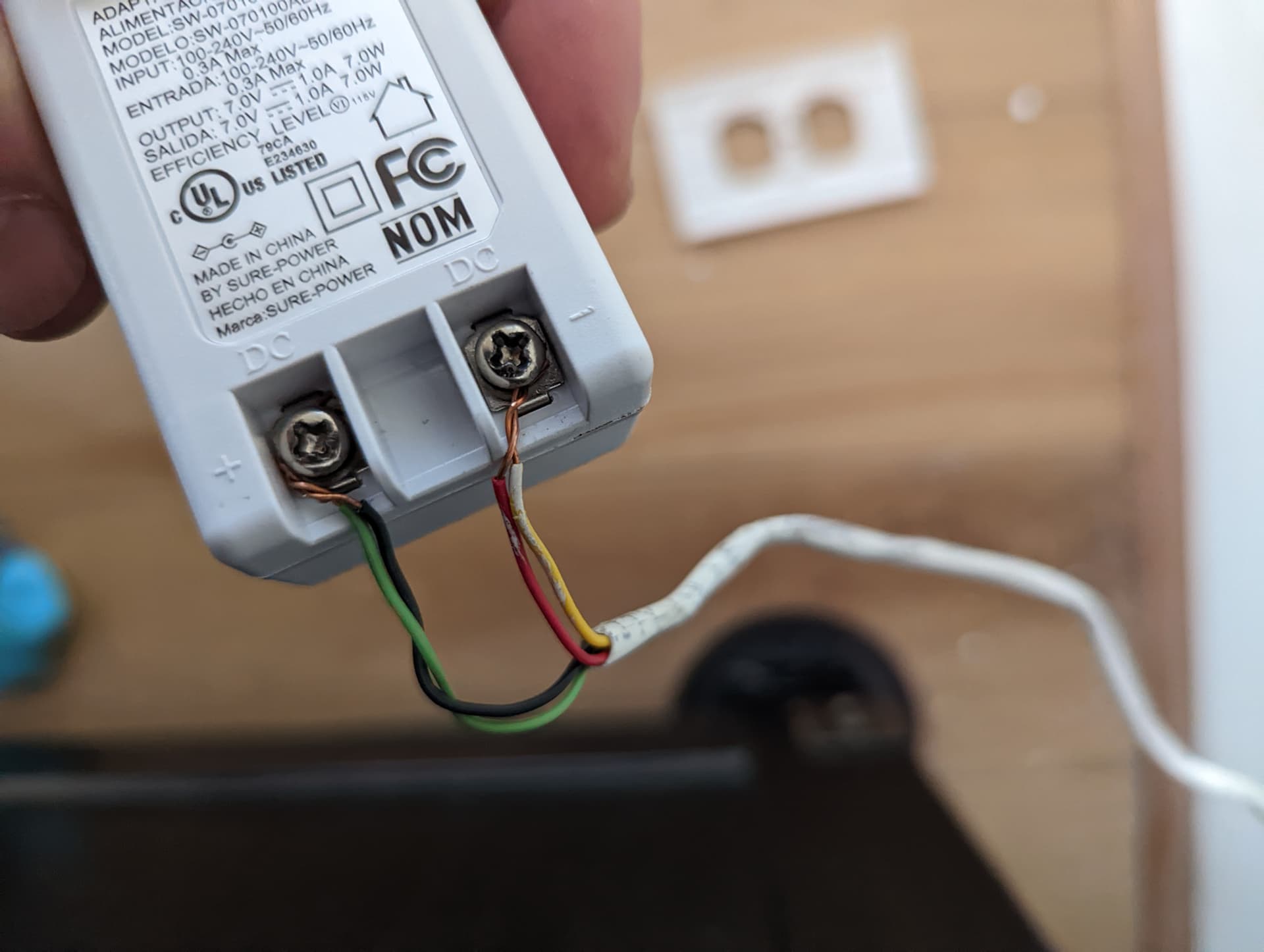
I connected the old wiring that supplied power to the Vista panel to the new IQ Panel 4 transformer.
A voltage tester shows power in the wires coming out of the transformer as well as in the spliced wires that go through the wall to the keypad. At the IQ Panel mount the voltage tester also shows power in the wires at the connection point. So basically the voltage meter is indicating power all the way from the wall to the mount, but when I mount the panel it’s not getting any of that power.
I’m thinking the problem has to be in the actual connection with the mount? Not sure what’s going on, but at least I identified the right wires.
I feel like I’m almost there, but I don’t understand why I’m getting that error message or how to troubleshoot.
Can’t really tell by the pictures alone but it’s possible your 2 twisted wires are not making it far enough into the connector and you aren’t getting voltage at the metal pieces the connect to the panel itself. But a touches tester will still show you voltage due to the close proximity.
As a test, I would undo the doubled up yellow/red and black/green and just insert the red and black into the mounting plate connector. If those are stranded cables, make sure the strands are twisted really good. Press down (towards wall) on the gray tabs as your insert the cable and push them in until they stop. Then lightly tug up on the gray tab.
UPDATE: I switched back to the cable with the barrel connector so the battery didn’t run out. When I plugged the barrel connector into the panel, I got the same error that it was not getting AC power.
Same outlet I was using before when the panel was working fine.
Voltage tester confirmed that AC power was going to the panel.
So I did a reboot and now the panel is just blinking random red and blue lights and the screen is black.
Try pressing and holding the power button on the side to see if the panel shuts off?
Without knowing how far your run is it’s hard to say on voltage drop concerns and doubling up the wires. Doubling may not be necessary, but it doesn’t hurt either.
Those individual wires are 22 AWG and I’m using single 22 AWG wires to power my panel from approximately 25 ft from the adapter and there is no voltage issues.
Also, I would re-arrange your cables so black is on negative an red is on positive, since that’s the “norm” as far as colors go.
And is there any reason you need the B connectors at the mounting plate side? Are the wires coming out of the wall too short to make it into he panel connector?
Okay I was going to try the power button but there’s a warning that it could cause data loss…
I’d say the distance is maybe 30 or 40 feet max, accounting for having to go to where the Vista panel is and then double back to through the wall to the keypad.
I could always put the transformer in the room with the Vista panel, but the outlet there is also powering the furnace so it’s kind of crowded.
Voltage tester confirmed that AC power was going to the panel.
This may just be a typo, but the transformer for the panel is 7V DC. Are you actually testing AC power at the panel?
Yes the dolphin connectors I assume are because the wires were too short.
Avoid all unnecessary splices, poor contact can lead to voltage loss. If the cable can be pulled out of the wall a bit, I would remove those splices there.
Is the Vista panel still powered up? Or was it powered via battery still while you were testing?
Did you disconnect the wires going to 4, 5, 6, 7 prior to testing? Because you may have been seeing voltage due to those being the keypad wires, simply spliced in with the module wires, suggested above.
I would seriously recommend identifying the cabling first, damage to the panel can result from improper voltage being applied.
Yep just a typo. I was just using a touchless voltage tester.
I tried to pull the wires out but unfortunately there’s no slack. That splice was from the old ADT system, which was working, so I don’t think that splice is the problem?
No the Vista panel is not powered up and the battery was disconnected. I’m just using the wires (none of which are connected to the Vista panel).
Yes I disconnected those.
I’m trying to think of what else it could be or what could be going on. The only wiring is the IQ 7v transformer → the pre-existing wires running to the room with the Vista panel → spliced to the wires running through the wall to the keypad (as seen in three photos above).
Is it even possible for incorrect voltage to be applied if the only transformer being used is the IQ 7V transformer that came with the IQ Panel?
Any idea what the red and blue randomly flashing lights indicated (they have stopped since the battery died).
Is it even possible for incorrect voltage to be applied if the only transformer being used is the IQ 7V transformer that came with the IQ Panel?
Yes, it is entirely possible that this is a case of voltage drop, but to know for sure and to troubleshoot, measuring the voltage will be required.
It is also possible that something else is on that wire circuit. Do you have any other keypads or modules or anything that might connect to the BUS terminals?
I would also triple check that you never applied voltage with the wrong polarity. This can damage the panel.
If the wires were shorted while the transformer was plugged in it can damage that transformer, another possibility here depending on whether or not any work was performed with the transformer plugged in.
The first necessary step would be to test voltage at the transformer to make sure it is outputting around 7vDC.
After that confirmation, test at the keypad end. What is the voltage?