I am looking to replace my standard thermostats with ADC-T2000s. I’ve installed these at a previous property so very comfortable with the wiring aspect, but this system is a bit more complicated.
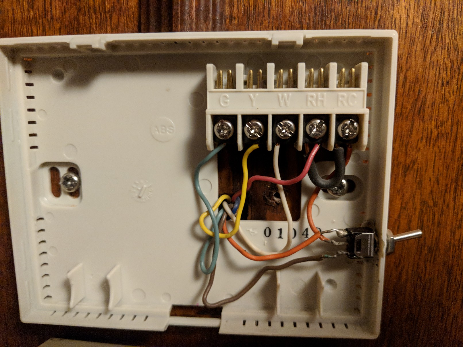
I have a dual-zoned HVAC system with two thermostats. Zone 2 is regulated by an automatic damper that opens and closes based on the temperature in Zone 2. The main thermostat has a manual heat/cool toggle switch that appears to be a custom addition by whoever installed the system several years ago. This effectively overrides the thermostat’s ability to digitally change from heat/cool, so that both zones are in the same heat/cool mode simultaneously. I’ve attached a photo of the wiring where you can see the toggle on the right side.
All of that sounds intuitive to me, but the presence of a manual toggle does mean changing the thermostats is a different ball of wax. Does anyone have experience with this kind of setup? I’m fine leaving the manual toggle in place for the ADC-T2000 if needed, since the need to switch from heat to cool mode happens only a handful of times per year. But I don’t want to fry the thermostat or (worse) blow the furnace.
I’ve had someone look at it and tell me to just leave it as is based on the “if it ain’t broke don’t fix it” mindset, but that is completely unacceptable to me since I wouldn’t get the automation and remote monitoring capabilities that I need.
Well, unfortunately without tracing the cable this is really hard to say definitively since it is non-standard, but my first question would be what type of HVAC you have.
My initial guess based on the image is that you have a heat pump system and the manual toggle is acting as an O/B terminal which are used to control the reversing valve to switch between heating and cooling on the heat pump, which that model of thermostat pictured doesn’t have, but is available on the ADC-T2000.
If you had a standard furnace the manual toggle would not serve any purpose - you would be energizing both heat and cool at once potentially, unless I am not understanding your description.
This effectively overrides the thermostat’s ability to digitally change from heat/cool, so that both zones are in the same heat/cool mode simultaneously. I’ve attached a photo of the wiring where you can see the toggle on the right side.
Have you tested and are you certain that is the function of the switch?
Could that manual switch be a manual control for the fan blower?
Ultimately, if you have a custom alteration make sure to be 100% sure of what its application is prior to making a change.
Actually, the system is a combined gas furnace with a/c. Furnace is in the basement and condenser unit is outside (so not an all-in-one packaged unit sitting outdoors). I live in a colder part of the country so heat pumps generally aren’t used here.
I am certain that the manual toggle switches from heating to cooling mode. The fan is separately operated by one of the OEM dials on the thermostat.
So the toggle does seem to be functioning as a O/B terminal of sorts even though this isn’t a heat pump. Could the existing thermostat be wired in “heat pump mode”, so to speak? Any other possibilities you could think of?
So the toggle does seem to be functioning as a O/B terminal of sorts even though this isn’t a heat pump. Could the existing thermostat be wired in “heat pump mode”, so to speak? Any other possibilities you could think of?
No, it would only apply to a heat pump with a reversing valve. Other than all on fan control, one other common manual switch found on some thermostats is for “emergency” heat, manually turning on a more expensive second stage of heat. This only applies if you have multiple heat stages.
I am not sure why the switch would feed 24VAC to two separate wires in this case. Does that switch have a middle position where neither wire is energized?
Are the W and Y wires even connected at the furnace?
I would strongly recommend contacting an HVAC specialist in order to determine necessary wiring for any thermostat replacing it.
I just thought I would close the loop on this thread, in case it helps anyone out there.
I took a gamble and wired the new ADC thermostat exactly the same way as the old, even retaining the manual toggle switch. I then set up the thermostat in the ADC interface as being connected to a heat pump (even though it is not). This way, the system would recognize the manual toggle switch, which is effectively acting as an O/B terminal.
Happy to report that everything has been working flawlessly for a few months now…for both heating and cooling.
Thought I would update this again, in case someone out there finds it helpful.
I just had my HVAC units replaced. Kept the same thermostat, which means that annoying manual toggle was still there, but I decided to try eliminating it so the thermostat could handle the heat/cool switching and allow me to use Auto mode.
I cut the orange (cool) and brown (heat) wires to the toggle and connected them directly to the thermostat. Brown is now on O/B and orange on Z. My reading indicates that this is appropriate for Rheem/Ruud units (which I have), while most other manufacturers would have the orange on O/B and brown on Y. So you may need to switch these if it’s not working for you.
I then disconnected the short orange wire from the toggle to Rc. It just provided power to energize the heat and cool cycles, but the thermostat does that itself so that wire is no longer needed.
Final step is to go into Advanced Settings>Installer for the thermostat on the ADC web site. I set HVAC type on Normal and Configurable Z Terminal as O/B Zoning. A new option will appear just above for O/B Terminal. This is where you tell it which wire you connected to O/B on the thermostat. In my case it was the heating wire (brown), so I set O/B Terminal to B. If you connected the cooling wire (orange), you would select O here.
Obviously your wiring color convention may be different (I understand the heating wire for many people is blue), so check your zone control panel to be sure you are connecting the appropriate wires.
Everything is working fine for me now, and with the thermostat handling heat/cool switching, I can do everything remotely and fully automate. One side note: I decided to have my HVAC pro disable the zoning system, so that all dampers remain open all the time. Without getting into too much detail, we just found the zones were unnecessary with the new unit and comfort is pretty well balanced without the dampers opening and closing. I only mention that to say this: I am confident this re-wiring of the main thermostat would still allow the zoning system to operate had we chosen to leave it active, but I haven’t tested it so can’t say with 100% certainty. So if you need to keep your zoning active, just be sure to trace your steps in case you need to backtrack.
Ok, one final update (hopefully). With fall temps settling in, I discovered that the outdoor compressor fan was running during the heating cycle. That would be normal for a heat pump, but I don’t have a heat pump. Turns out that the orange and brown wires should be wired opposite of what I did initially. So in other words, orange to O/B and brown to Z, REGARDLESS OF HVAC SYSTEM BRAND. The brand apparently only matters for true heat pumps. Since changing the wires and configuring on the ADC web site, the outdoor fan no longer runs during heating cycles.
The adventure continues. When I turn on the fan with the thermostat in heat mode (but not calling for heat at that moment), why would the thermostat activate the outdoor A/C compressor fan instead of the furnace blower? Again, the furnace blower runs and the compressor fan remains idle when the thermostat calls for heat, which is proper operation. So this issue only applies when I want to run the fan to circulate indoor air, for example.