Greetings,
Recently disconnected my panel to clean-up wiring/cables in the box. I am having issues getting the system back online. My setup is a little different, as I am not using AC power. I have 14vdc adapter connected to an UPS that runs everything. Now, I had everything working before with this setup, but can’t seem to get it right this time.
My initial focus is on the takeover module; the red light flashes when applying power but never stays on. Also, don’t get any lights on the NX-8V2 (but can’t recall if I did before or not).
I’m just looking for another brain to throw some info at this… I can’t think of anything else to try.
My setup is a little different, as I am not using AC power. I have 14vdc adapter connected to an UPS that runs everything.
Can you describe this a bit more? The issue is likely here.
In a typical TAKE-345 installation with the old panel present the following should generally be true:
- The TAKE-345 is powered off of the old panel's 12VDC aux output, and battery is connected to TAKE and old panel battery circuit. The TAKE should not be powered directly off the 2GIG Panel transformer.
- The 14VDC transformer would be for the 2GIG Panel only.
- The Old Panel would be powered off of a 16.5 VAC transformer. This would need to be plugged in for the TAKE to receive DC power from the panel and for the panel to charge the battery.
So, what I did (initially due to limited material) was wire the old panels DC connection AND the TAKE DC connection (red&black that normally go to battery) to a 14vdc adapter. The “G” and “12V” terminals on TAKE, I wired to KP COM and KP POS on the old panel. It worked - no issues. I wasn’t able to get the red light (power I guess) on the TAKE to remain on.
Currently, if I power the old panel with 14vdc first, then connect the TAKE to the same leads, The red light on TAKE comes on, but it seems to be dimmer than expected. When I connect the TAKE to the KP COM/KP POS on the old panel, the red light goes out.
I don’t really understand this sequence of powering and the importance of it. I don’t understand why I should even need to power the old panel…Am I not just using it basically as a terminal strip?
Just noticed in the 1st paragraph, " I wasn’t able to get the red light (power I guess) on the TAKE to remain on." This is recently after I disconnected and rerouted the cables. Not from before.
The NX8 panel cannot be powered off of a 14VDC transformer.
The NX8 is powered off of a 16.5 VAC transformer.
The old panel (NX8) is used in this scenario as a battery charging circuit and housing for the brick battery which acts as backup for the TAKE345.
Based on the description I’d like to be certain about what is wired to what. Could you provide a photo of the transformer you have connected to the AC input on the NX8? Any photos of the wiring would be helpful in getting this resolved, but just from the description it sounds like the wrong power supply is being used.
was wire the old panels DC connection AND the TAKE DC connection (red&black that normally go to battery) to a 14vdc adapter.
An NX-8V2 has no DC input. By adapter, do you mean a separate power supply board? Or do you mean a plug-in transformer?
The 2GIG GO!Control Panel runs on a 14VDC power supply. Only the Go!Control Panel should be wired to it. (Or GC3, if you have a GC3 instead)
Jason,
I don’t have anything connected to AC on old panel. I’m only using the 14vdc; it is actually the power supply for the 2GIG GO PANEL. I realize this setup isn’t recommended and I haven’t seen anywhere online where others are using this. I got it connected thru a lot of trial & error originally. It was not based on my knowledge of this system - I know nothing. But, it was working with just the 14vdc for ~6 mos. No 12vdc battery, No AC voltage.
Is this not possible? I mean, if the devices just need 12vdc, shouldn’t I just be able to give them the pwr and they work? I was under the impression I was just utilizing the NX board as a terminal strip, more or less. Rather than having a back-up battery, I thought I was just wiring everything as if the system was running on battery, but it was a continuous dc voltage.
Do the red&black wires (that usually connect to battery) power the board in case of power outage? In this case, If you supply 14vdc shouldn’t the NX board work without having AC power? If not, maybe I have something connected different than I did before.
Essentially, what I need to do is power the TAKE with just a 14vdc adapter. It was working with this configuration before, I just don’t know exactly how.
*attached PDF of wiring schematic previously used - not sure if this will help but I’m lost at the moment.
NX-Wiring-Notes.pdf (1.54 MB)
Ah, I see, so you are not using a backup battery, and you are not trying to power the old panel with the transformer.
You are essentially just powering the TAKE directly from the Go!Control’s power transformer.
Thank you for the description, it helps clarify what is being used. We’re happy to help out!
See this video for an installation tutorial on the TAKE-345.
Voltage that is accepted by devices is always +/- a bit from the exact specification. It will depend on the device. The TAKE-345 can operate on the same 14VDC transformer, but I would not recommend it. I would encourage connecting the 14VDC transformer only to the Go!Control Panel DC power input.
Currently, if I power the old panel with 14vdc first, then connect the TAKE to the same leads, The red light on TAKE comes on, but it seems to be dimmer than expected. When I connect the TAKE to the KP COM/KP POS on the old panel, the red light goes out.
Also, don’t get any lights on the NX-8V2 (but can’t recall if I did before or not).
You would not see any lights on the NX8 in this case, you are not powering the old panel.
You’re essentially using the old panel terminals as a wire connector, nothing more in this case. It would be no different to directly connect the wires to the TAKE from the 14VDC power supply. The wires would need to go in the same terminals, + + in one, and - - in the other.
Afterward, power cycle your Go!Control panel by entering programming and exit saving changes. Ideally you would want to be able to power up and power down the TAKE and the Go!Control Panel independently, but the setup described precludes that.
Does the reboot resolve the issue?

Man, thanks for the info. I was really looking for some sort of expert guidance - just DIY blindly here. I would like to pick your brain a bit…
- So, I don’t need to connect the red/black wires for NX panel’s battery termination AT ALL? What does this connection actually do?
- Do I have to use the resitors? Or are they more just added security for the system.
So, I don’t need to connect the red/black wires for NX panel’s battery termination AT ALL? What does this connection actually do?
It is used to connect to a backup 12VDC brick battery. You should not connect anything other than a battery to the battery terminals.
Are you also attempting to power wired motion detectors and glass break detectors? Those should not be powered off the same 14VDC 2GIG transformer.
Ultimately the way you want to do this is properly power the NX8 board with a 16.5 VAC transformer connected to its AC input. I would very strongly recommend powering the devices per manufacturer instructions.
Do I have to use the resitors? Or are they more just added security for the system.
No, resistors have no function with the TAKE-345. The TAKE-345 does not look for a specific resistance value, just resistance under a maximum limit. Resistors on the sensor zone wires can be removed if using a TAKE-345.
OK. I wired in (1) sensor and reboot the GO pnl. It shows no faults and system ready to arm; which is odd b/c all other sensors are disconnected. No indication on panel when triggering sensor.
It appears the GO pnl is not communicating with the TAKE.
Is there a way to verify communication to the TAKE switch?
When you reboot the panel, it will boot into a state that assumes all sensors closed. It will not register an issue until the device signals that there is one.
If you’ve not made changes to programming, it is likely you have an issue with power application or the GND is not connected properly so that sensors can physically be detected opening.
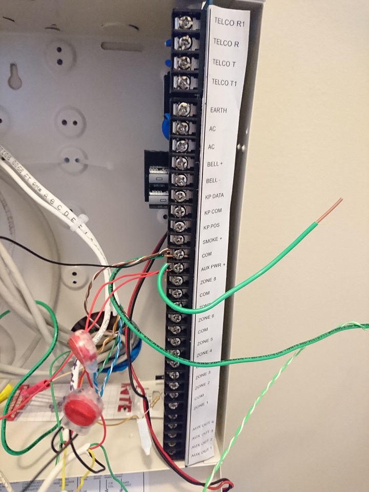
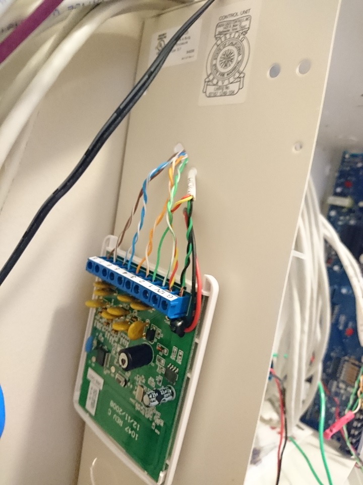
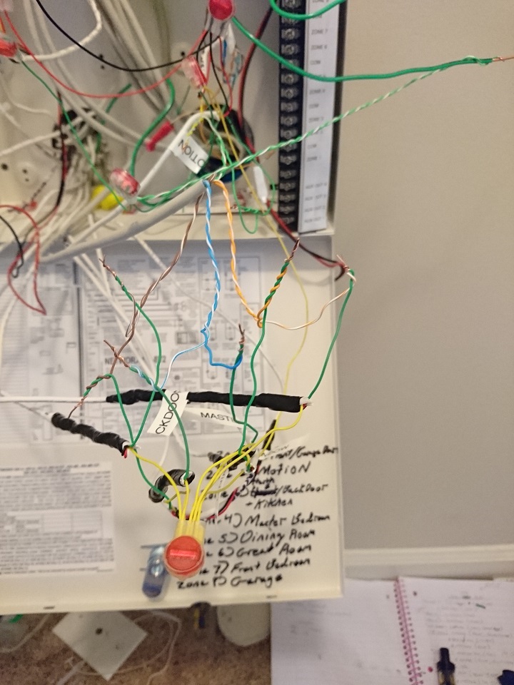
Can you please post a photo of your old panel board, TAKE module, and wiring?
See the installation diagram attached in a response above. See how the GND wires all connect before being wired into G? One wire from each sensor must be connected at some point in the circuit to the TAKE G terminal.
I can’t seem to figure this out. I tried omitting the NX board and still couldn’t get any sensors to trigger. So wired back into just 2 of the terminals on the board, Now, when applying power to the TAKE battery cable-nothing happens; When I touch the 12V wire to power, the red light flashes but doesn’t remain on.
I know I should have AC if I plan to use the NX board, and a battery, but I want to just see this work before investing further. I don’t understand why not having a separate board will prevent this system from working.
- Pics are attached
Rewired without the NX panel and only connecting 12V and G to the TAKE. When power 1st applied, the red light turns on/off. Rebooted GO panel and sensors are working. The red light never came back on the TAKE, though.
Now, when applying power to the TAKE battery cable-nothing happens;
Unless you are connecting the TAKE battery leads to a battery, you should not be connecting it to anything.
Do not apply a plug-in transformer to the battery input.
I don’t understand why not having a separate board will prevent this system from working.
Not using the board won’t stop it from working, but there are a lot of questions in a non-standard installation. There are a few likely reasons for the faulty function:
- Incorrect terminals wired to power. This could possibly damage the device. Never connect the DC power source to anything other than G and 12V on the TAKE-345 terminal board. You’ll need to follow polarity, Positive to 12V and negative to G.
- Each sensor zone will have two wires associated which complete the detection circuit. One of those wires must be inserted into the Zone numbered terminal on the TAKE. The other, which would have come out of the COM terminals must, in some way, be wired to the G terminal of the TAKE. Since standard installation instructions are not being followed, you’ll need to verify that the detection circuits are complete and connected to G (GND). I cannot tell exactly from the photos, but it looks like G may not be connected to the zone commons. Can you confirm?
As a general note, it is recommended to use wire connectors of some kind. Twisting wires together and leaving them bare has a high likelihood of resistance fluctuation, wires separating, or wires shorting. We typically would use B crimp connectors. Small wire nuts are fine as well.
Also, while applying power you should always secure the wire to the intended terminal and then plug in the power supply to wall power. It’s not clear from the description, but just in case, if you leave the wire energized and manipulate the wire, removing it and fastening it to terminals, you can cause shorts and damage the TAKE (or whatever device you are working with.)
Rewired without the NX panel and only connecting 12V and G to the TAKE. When power 1st applied, the red light turns on/off. Rebooted GO panel and sensors are working.
Ah, alright that means the commons are still connected to G.
If you were previously connecting those to the battery wires instead of the 12V and G terminals and nothing was wired into G, that would mean the sensor detection circuits just weren’t completed.
All the common wires should be connected to GND. The twisting of wires is just for T/S purposes. I plan to make everything more permanent & clean install (where is how all this got started).
The company that originally installed this used different color wires on some of the runs for common; some of the sensors were jumpered together in a configuration I haven’t been able to figure out.
I’m out to try and find a AC xformer & batt right now.
some of the sensors were jumpered together in a configuration I haven’t been able to figure out.
We’re happy to help if you are looking to identify the wires.
If multiple sensors are on the same zone, the wires would be spliced in series. This makes it so whenever any of those sensors open, the circuit opens.
Gentlemen, Thank You for all your help.
I believe my main problem was not initially REBOOTING THE PANEL after cycling power (along with some wiring mistakes, most likely). I was never able to locate a AC transformer on hand, so, currently have the TAKE powered by 14VDC xfrmr on 12V & G terminals. Installed a battery to the TAKE’s battery leads - Not sure if it is going to charge the battery, but I have the 14vdc connected to an UPS that will power the system 3-5 days without power.
If multiple sensors are on the same zone, the wires would be spliced in series.
Some of the sensors are not working and I believe this is the reason (i.e. front and side door only alarm when both are open; nothing when individually). I thought I had a good idea of what wired in series meant, but I was expecting the sensors to have the same color wires connected. This is not the case… They both have Yellow/Green connected. I’ll do some more research online and sure I’ll find some info on this.
Again, thank you for your time.
Installed a battery to the TAKE’s battery leads – Not sure if it is going to charge the battery, but I have the 14vdc connected to an UPS that will power the system 3-5 days without power.
No, the TAKE-345 will not charge the battery and it will deplete. You would need a charging circuit, like that of the original wired panel, or something like a Honeywell HPL-624
You can find a 16.5 VAC transformer here.
thought I had a good idea of what wired in series meant, but I was expecting the sensors to have the same color wires connected.
Wire sheath color has no bearing on function and aside from DC power application, phone, and keypad connections, no standard is typically followed.
A description of series vs parallel circuits can be found here.
Some of the sensors are not working and I believe this is the reason
If you have powered sensors, like motion detectors and glass break detectors, they would require 12VDC. Are they receiving power?