Is anyone here familiar with the Radionics D8112? I’m installing (DIY) a 2GIG system and hoping to utilize most of the passive zones (door sensors in particular) installed to the D8112 with the 2GIG system.
The 8112 seems to be working okay and its control panel is lighting up various zones as doors open or motion sensors are passed. It’s quite old (35+ years). The control motherboard is in an attic space not far from the 2GIG go control so I expect the wireless transmitter in the TAKE to be able to communicate clearly with the 2GIG.
Based on the Surety videos and 2GIG documentation, as well as radionics documentation, I feel confident in being able to run AUX power to the 2GIG TAKE and wire in the zones. But I do have a few questions and would appreciate any assistance:
The 8112 whines occasionally, the buzzer (not the whole tripped alarm) and the control panels in the 8112 will beep and require a “Command 4” which is basically a zone reset. I wonder if the panel will continue to do this after I remove the zones from the motherboard and forward it to the TAKE?
The 8112 zone wires have resistors on them. Do I keep those resistors on the wires? Now I’m starting to wonder if the zone wires with resistors are in the common ports (not the zone control ports). If that’s the case I think those don’t go anywhere right?
What gauge wiring should I get to cap and extend the zone wires to the TAKE? For the jumper wires? 18 AWG? Also, the video makes it look like I can use two zones for each of the pair in the jumper wires, I guess that’s ok to do.
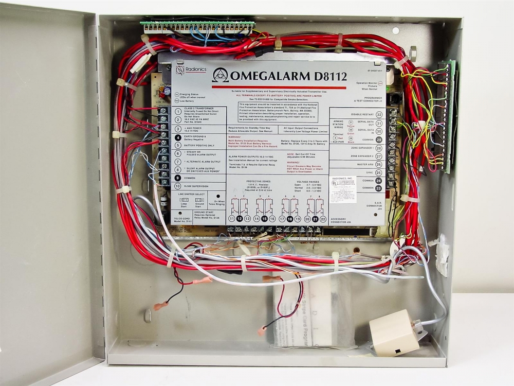
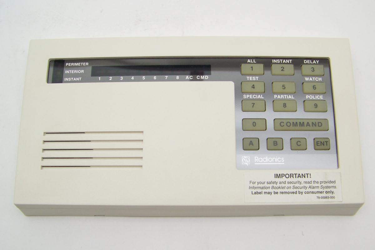
This one seems obvious but is the most elusive to me: I don’t know what physical wired zone on the motherboard goes to what door/motion sensor on the Radionics panel? In other words, even though Zone 1 on the radonics panel might flash 1 when it’s tripped, I don’t know what that corresponds to on the motherboard itself. Is it 11, 12, 24? It looks like it might not matter, because the go control console will be able to learn each of these zones as I trip them in learn mode, but I also think there’s over 8 zones and I don’t want to wire in any motion detectors, only doors so I’m trying to figure out “what’s what” before I do the actual wiring.
This probably doesn’t make a ton of sense but I would appreciate any help the community can offer. Here’s some example pictures of the Radionics motherboard and control panel (our control panel might be more than 8 zones, though) along with a link to their installation manual. Thank you!