I’m preparing to mount the PG9935 wireless shock sensor to the wood frame of a sliding door. (I’ve seen the recommendation to attach it to the sliding door itself, but I’ll try it with the original installation instructions first.). Two questions:
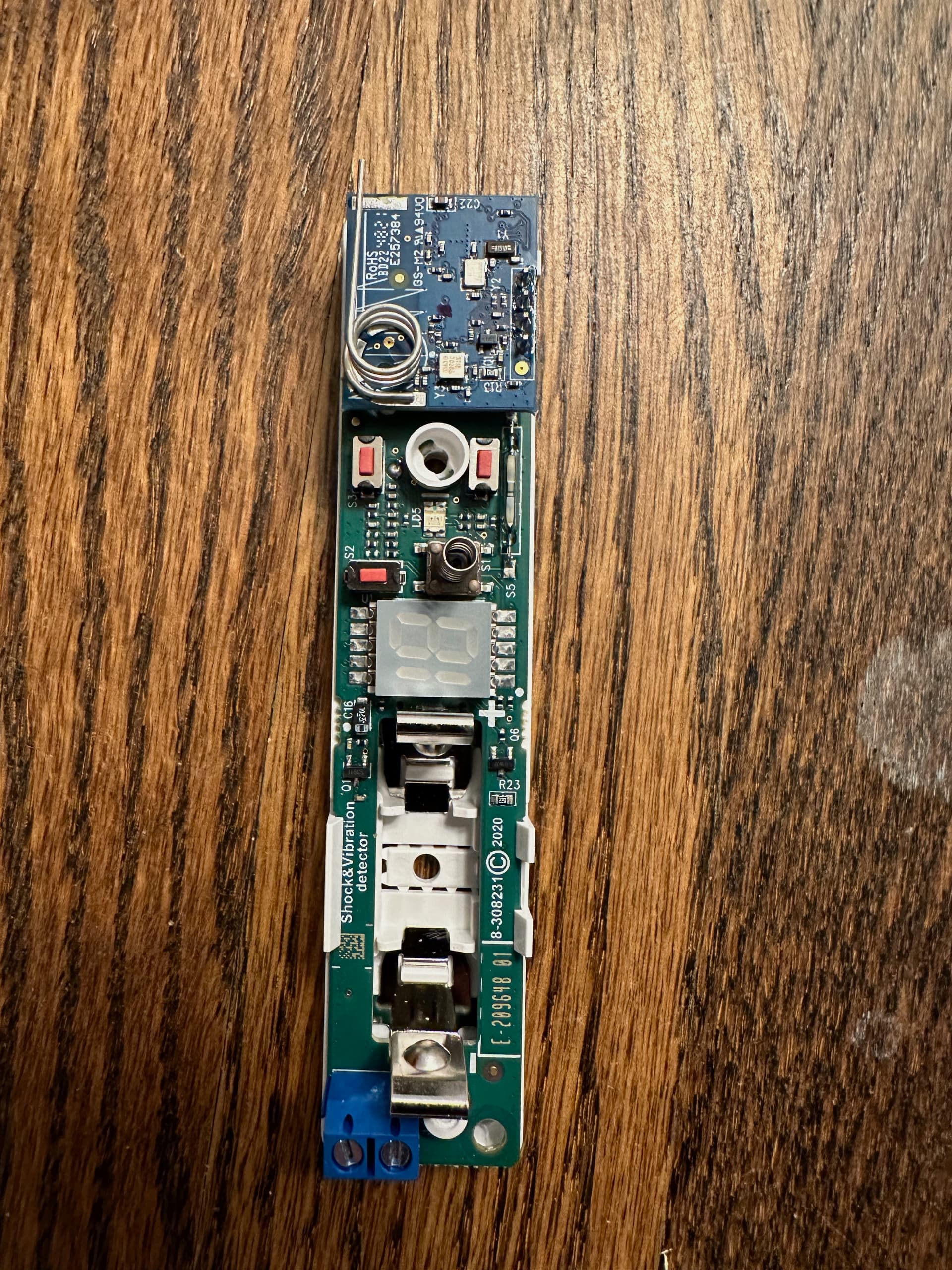
Three large screws are provided and seem to be indicated for mounting. In the attached image, which I think is right side up, I see a screw hole in the lower right, and a screw hole in the breakaway segment visible about a quarter of the way up in the center. I can’t figure out where the third screw goes. It seems like it should be in that white tub below the top circuit board and between the two red up/down buttons, and above the front tamper switch. But the provided screw doesn’t fit through that tub. Are we supposed to somehow remove the circuit board from the base? Or where does the third screw go?
Are the provided screws suitable for mounting onto a wood frame? Drywall anchors were provided, so I’m not sure if those are intended for drywall (I strain my mind a bit to think why part of a wireless shock sensor would be mounted on drywall.)
Attached to this post is an image illustrating the specific locations where screws should be inserted for the assembly and mounting of the PG3395 Shock Sensor.
The PG3395 features a primary set of mounting holes, typically two, for the base attachment. Additionally, there is an extra spot for a tamper-proof screw on the front plate. Please note that the bottom right hole is not designated for mounting purposes. There may be extra screws to account for losing some.
The screws provided by the manufacturer with the Shock Sensor are intended to be used for mounting. They should be sufficient to fit through the mounting holes and into a wooden frame. However, if a provided screw does not fit a particular spot, it is crucial not to force it or alter the device in any way that might cause damage. You may need to reach out to the manufacturer with images to confirm the correct screws, please let me know if you need assistance.
The included drywall mounts can be used for drywall installation if necessary. The key to effective shock detection is the firm attachment of the sensor to the surface from which it will monitor for vibrations.
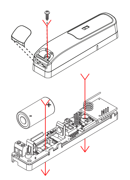
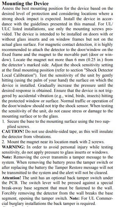
For further guidance, I have also included the manufacturer’s mounting instructions for your easy reference.
Great, thanks for the clarification. I checked again, and while I can’t push the screw through the plastic tub piece near the top of the device, it does screw in. I wasn’t expecting that…
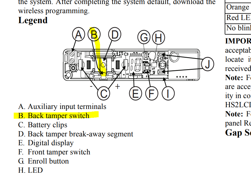
Somehow my recollection about PowerG sensors is they typically have 2 regular mounting holes then the special one through a breakaway segment, so I was expecting the same here especially since the sensor is larger. I also am perplexed by the statement that the “back tamper switch [is] under the PCB” and the “switch lever will be pressed against a special break-away base segment” when that segment (labelled D in their diagram) is clearly under the battery compartment which has no apparent switch. Anyway, that’s just my predilection for taking technical instructions too seriously, and resolving my confusion is not important for my application.
Out of curiosity are those installation diagrams with the red arrows in the public domain? I couldn’t see anything like it in the official DSC/Tyco/Johnson instructions.
Thanks much! Given other people’s reports, I’m curious to see if the shock sensor will actually work…
I will reach out to the manufacturer today for clarification regarding the tamper switch and the break-away segment and follow-up in this post. There was confusion from my side as well, the installation instructions are not clear about the screw holes, and I will ask about the additional bottom right hole since it is not addressed.
The diagram with the red arrows I created from a screenshot using the manual.
Best of luck with the installation, let me know if you run into any other issues, I am here to help!
I apologize for the delay, but after some back and forth communications I was able to get good information to provide.
I will attach an image provided by the technician. The bottom hole of the device can be used as a screw hole, it seems there was a discrepancy with the documentation as you pointed out. This is located at the bottom left of the provided image. The technician was mostly concerned with the screw in the small cup between the “J” identifiers and the one for the back break-away segment (D) as one will hold the device and the other will trigger an alarm when broken off. It is suggest to mount these as securely as possible to best detect vibrations, so a third screw would help. Highlighted is the back tamper switch (B) and the other is located at (F).
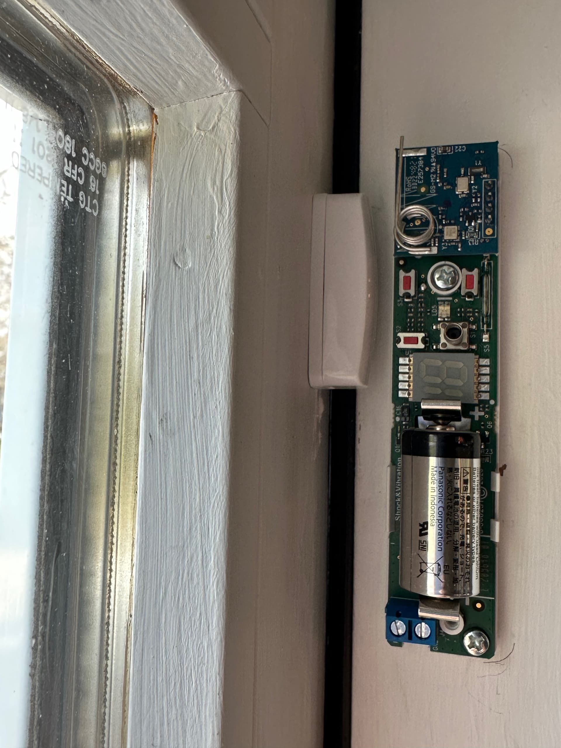
Thanks for this; I’ve attached a photo of how I mounted the sensor on my sliding door. The open/close detection works just fine. When conducting the shock sensitivity calibration, I get:
absolutely no response if I hit the window or the frame of the sliding door (where the magnet is mounted) with either my palm or the blunt end of a screwdriver, even though the magnet is visibly shaking.
a reading of 2 if I hit the fixed frame (where the detector is mounted) with my bare hand
a reading of 7-8 if I hit the fixed frame with the blunt end of a screwdriver
a reading of 4 by simply opening the sliding door
no shock response if I slam the sliding door shut
This seems to suggest I should mount the detector on the sliding door and the magnet on the fixed frame. This has been previously recommended for related applications in this forum, but it appears to contradict the installation instructions from Tyco: “For magnetic contact detection, it is highly recommended to attach the detector to the door/window on the fixed frame and the magnet to the movable part (door or window).” I somehow assumed the sensor would detect shock vibrations of the magnet, but this seems not to be the case. Are the Tyco instructions simply in error for reliable shock detection on a door or window? What’s odd is a google search for “mount shock sensor on sliding glass door” generates similar advice across products and security product vendors.
I’d like to just verify here:
I have no misunderstanding or something further to try in my application before reversing the mounting of the magnet and sensor, and
For the benefit of other users, that the Tyco installation instructions regarding sensor and magnet placement are incorrect, rather than simply suboptimal in certain applications.
Thanks much – this experience suggests this forum may be the most accurate and comprehensive source of information on DIY security!
For sensors that are magnetic open close only, that is the recommended installation instruction, usually. Whether they intended to copy paste that onto this particular sensor I couldn’t say, but it would be sub-optimal for some installs and impossible for some.
In your case in the image the sensor is on a perpendicular surface with a gap in the solid materials. There is no mechanism for the shock to transfer. Other frame styles aren’t affected like that though, so individual mileage will vary.
In general though you will definitely get better shock results with the sensor on the frame of the moveable part. In this case it should be moved to the moveable window frame.
Following up with a reply from a technician from DSC that reached out today wanting to provide me more complete information about the manual’s instructions. It was stated the bottom hole was optional if the screw is not used in the tamper break-away section.
That is correct from the follow up I received. The main screw in the “cup” and then either a screw in break-away segment to enable the tamper switch feature, or the bottom if not wanting to use that option.
Following up to confirm that mounting the sensor on the sliding door and the magnet on the fixed frame led to workable shock readings when the glass is struck with the back of a screwdriver.
One question – is the accumulation feature supported, and if so, recommended for residential use? I don’t see anything about accumulation on the panel, but the device has local programming of shock level and accumulation on/off.
Accumulate is a local feature on the sensor which will cause it to trigger based on continued activity below the threshold of detection. It is not configurable at the panel, just on the sensor itself.
I’ve not used it a lot on the PG9935, but it is I believe intended for someone trying to tamper with a window or door rather than bash it in. Always turn it off before testing detection threshold for striking the glass.