I have my system all set up and was hoping to use a single RE101 to handle a cluster of windows in my garage with the wired terminals. I tried different configs, but could never get the sensor to detect the wired loop. I have a few normally open contacts with magnets.I tried the inner terminal and registered the sensor with the Qolsys so it see the second ID for the wired loop, but does not seem to detect whether the wired loop is open or closed. Is the wired loop for regular N/O contacts?
The wired sensor terminals on the RE101 are for normally closed (N/C) sensors. Just about all security sensors are normally closed. Are you sure yours are normally open?
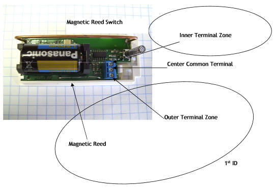
There are 2 wired sensor inputs on the RE101. You can connect a sensor loop to the inner terminal zone and the center common terminal. Then you can connect another sensor loop the outer terminal zone and the center common terminal.

Do you have a multimeter to measure the resistance on your sensor loops?
I believe the terminology is Normally Open and then when the magnet is preset they are closed completing the loop. My switches are closed when the magnet is present. I have tried both loops. My understanding according to the doc is the out terminal shares the same ID as the wireless sensor. If you want to use the inner terminal you have to set the panel to discover a new sensor and then pull the batter and while holding in the tamper switch and insert the battery. That causes the sensor to be discovered with a secondary ID for the inner terminal loop. The panel discovers the secondary ID fine, but can never get a status. I have to dig out my ohm meter, but these were wired and working fine with my old ademco system just before I pulled it out.
You’re right, except that in security sensor terminology the “normal” state is when the magnet is present and the circuit is closed. The “active” state is when someone opens the door/window, removing the magnet, opening the circuit and triggering an alarm.
Yes, the outer terminal shares the same ID as the reed switch which is the one printed on the sensor.
If you’re having trouble with wired sensor loops an ohm meter is extremely useful and worth digging out. You may have end-of-line resistors or even corrosion on your wired loop so it will be useful to see what resistances the loop switches between when you open and close the sensors.
Another method that’s very useful is testing the sensor’s wired terminal themselves with just a jumper wire. Remove the existing sensor loop from the equation and just verify that the RE101 works when you connect and disconnect a jumper wire because you know that will provide 0 and ∞ Ω.
Well I got it working. I think it was working all along. I find the wired zone quirky. It seems there is a delay for it to pick up the wired loop to change condition. Also on occasion or will show open/closed even though I opened it. I buttoned everything up and will do more testing, but it is working now. I may retire the windows and put some new senors in I had purchased since these sensors are 20 years old, but appear to be working fine.