Alarm.com Introduction
Alarm.com’s LTE module can be used on NetworX 4V2, 6V2, 8V2, and 8E
panels. The module interfaces with the NetworX panel data bus and is
powered by the panel. The Alarm.com bus module for NX is made of two
parts: A bus module (NX-592E) that connects to the panel via 3 bus wires,
and the LTE radio board that plugs onto the NX Gateway board.
Installation Tips
Use the following tips to help guarantee your success with the Alarm.com
NetworX LTE Module:
- Make sure you create the customer account on the Alarm.com dealer
website at least 24 hours before installation. - Use the Radio Status LEDs on the module to check the signal strength
before you permanently mount the module. - Do a phone test to initiate communication
Installation
Before you install the system, the module must be activated. Click here to get started.
Use the following installation guidelines:
• The module draws a maximum of 65 mA (continuous) in PowerSave
mode and 100 mA (continuous) in Idle Mode and Connected Mode
from the panel. The module can draw up to 1600 mA (instantaneous
peaks) from the panel.
• Do not exceed the panel total output power when using panel power
for bus devices and hardwired sensors (refer to your panel
documentation).
• Use three-conductor, 22 or 18 gauge stranded wire to connect the
module to the panel. 22 gauge 40 ft max distance or 18 gauge 90 ft max distance.
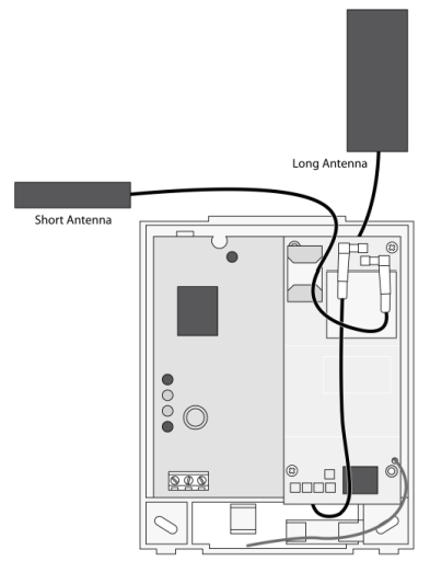
Module Mounting
- Press down on the top of the enclosure cover and set it aside.
- For optimal signal strength the antennas should be placed as far away
from the module as possible and as far away from each other as possible.
The recommended antenna orientation is shown in the figure below.
- Place the module back plate on the wall at the desired mounting location,
check for level, and mark the three mounting holes and the wire access
area. Be sure to leave at least 12 to 18 in. (30 to 45 cm) above
the back plate for the antenna. - Set the back plate aside and drill holes at the mounting and wire access
area locations. - Use wall anchors where studs are not present and secure the back plate to
the wall with the enclosed screws.
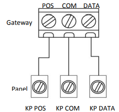
Wiring
- Remove panel AC Power and disconnect the backup battery.
- Wire the module to the panel POS, COM and DATA terminals as shown in the figure below
Powering up the module
- Verify that all wiring between the panel and module is correct.
- Connect the backup battery and restore AC power to the panel.
Note: Whenever any module is added or changed, you must remove panel power and reapply it for the panel and module to communicate successfully. - Verify that radio status LED 1 is not flashing any errors.
- Also, verify that LED 4 is flashing a signal level of two or higher. Otherwise, relocate the module. If LED 1 and LED 4 are not flashing, and LED 2 and LED 3 are flashing together, the module is in PowerSave mode and the battery needs to be charged.
- Perform a manual phone test on the NX8v2 by pressing *44 while the system is disarmed (Make sure that panel’s Location 37, Segment 2, Bit 7 is set).
Note: if Location 37, Segment 2, Bit 6 is set, performing the phone test will trigger the local siren. To avoid triggering the siren when performing the phone test, make sure Bit 6 is OFF.
The panel will not show any indication that the phone test signal has been sent. You can check the radio status LEDs L3 and L4: L4 should be blinking on for 2 seconds and off for 2 seconds. L3 will blink once briefly as soon as you press *44. If the account is reporting to a Central Station, wait for a minute and check with the Central Station to see if the phone test signal was received correctly. The phone test is also used by Alarm.com to set the module’s parameters the first time the module is powered up. It ensures that Alarm.com will receive the sensors list and any other information required for proper signaling.
Enrolling the Module
The NX control panels have the ability to automatically find and store in memory the presence of all keypads, zone expanders, wireless receivers, output modules, and any other device on the keypad bus. This allows these devices to be supervised by the control panel. To enroll the devices, enter Program Mode using the procedure outlined in the control panel installation manual. When you exit Program Mode, the control panel will automatically enroll the devices. The enrolling process takes about 12 seconds, during which time the “Service” LED will illuminate. User codes will not be accepted during the enrolling process. Once a module is enrolled, if it is not detected by the control, the “Service” LED will illuminate. When initially powering up, the control panel automatically performs the device enrollment process.
Radio Status LED’s
| LED | Function |
|---|---|
| L1 | Error LED. Flashes 1 to 8 times in an 8-second interval to indicate specific error. See Table 5 for errors and common fixes. |
| L2 | Panel Communication and Z-Wave status messages. Flashes every time the module communicates with the panel and flashes in patterns to indicate Z-Wave status. |
| L3 | LTE Communication. Flashes every time the LTE signal level is checked and when packets are exchanged with Alarm.com. |
| L4 | LTE Signal Level. Flashes 0 to 5 times to indicate signal strength, or toggles on/off slowly when communicating with Alarm.com servers. |
| L5 | Z-Wave Error LED. See Table 6 for error descriptions. |
LED L1 (red)
L1 flashes when there is an error. The number of flashes indicates the error number. If there are two or more errors at the same time, the errors will flash one after the other. The LED will stay off for at least four seconds between errors.
| Number of Flashes | Error and solution |
|---|---|
| 1 | Module cannot communicate with the panel. Perform a power cycle on the panel. If the error persists lift the module out of the panel and re-insert it. If the error is still observed try a different module. Finally, if that does not fix the problem try a different panel. |
| 2 then 4 | The module provisioning process could not be completed. |
| 2 then 5 | The module provisioning process could not be completed because the module is currently roaming on the carrier’s network. |
| 3 | The module is trying to register on the LTE network. If it persists for more than a few minutes, the module is having problems registering with the LTE network. Check L4 for signal level. If signal level is lower than 2 “bars”, change the panel’s location or use a remote antenna option. If the signal is good, the module may be roaming on a LTE network that does not partner with our LTE providers. |
| 4 | The module is registered on the LTE network but cannot connect with Alarm.com. Contact Alarm.com Technical Support. |
| 5 | Radio portion of the module is not working correctly. If this persists for more than a few minutes the module may need to be replaced. This error is extremely rare so verify that the module is flashing 5 times. |
| 6 | This is an error only if it persists for more than a minute. Otherwise, it’s just an indication that the module is fixing an unusual condition regarding communication with the LTE network. |
| 7 | There are bit sets in Location 21 that prevent Alarm.com from getting the sensor list from the panel. In Location 21, segment 1, if bits 5 and 6 are set the module can not retrieve the sensor list. Note that bit 7 will prevent location 21 from being displayed at the keypad. Bits 5, 6 and 7 can only be set via the Downloader program. This could also mean that the module is not compatible with the current panel type. |
| 8 | If it persists, the account may have been set up incorrectly. Contact Alarm.com Technical Support. You will be asked to check the serial number of the module. |
LED L2 (yellow)
L2 flashes with every communication between the module and the panel. Normal pattern calls for a series of quick flashes every two seconds in Idle Mode or four seconds in PowerSave Mode. It also occasionally flashes in patterns to indicate Z-Wave status. See Table 6 for a description of various possibilities.
| LED 2 | LED 5 | Device Status or Error | Description |
|---|---|---|---|
| 4-blink | Add Mode (lasts 120 seconds or until a device is added) | In this mode you can add a device to the local Z-Wave network. Devices cannot be added to a network if they are already a part of a network | |
| 2-blink | Delete Mode (lasts 120 seconds or until a device is deleted) | In this mode you can delete a device from a Z-Wave network. A device can only be in one network at a time, and must receive a “delete” command before it can be learned into a new network | |
| Solid | Successful add node/remove node/replication (lasts 60 seconds) | After receiving this signal leave all devices by the LTE module for 1 minute. Locks must be left next to the module for 4 minutes | |
| Solid with one blink | Add node attempt failed because node already in network (lasts 60 seconds) | Device you attempted to add to a network is already in a network, and must be “deleted” before it can join a new network | |
| 2-blink | No other nodes are in the network (lasts until a device is added to the network) | No devices have been added that can be controlled by the LTE module yet. See above for instructions on how to add devices | |
| 5-blink | Learn mode error (lasts 60 seconds) | The device was not successfully added to the ZWave network. | |
| 6-blink | No Home ID present (lasts until the module connects to Alarm.com and is configured) | When the LTE module first connects to Alarm.com it is configured with a necessary unique network ID |
You can find more information about installing this Alarm.com communicator in the Installation Manual