Introduction
This guide will show you how to install an alarm.com communicator TL880 on a DSC Neo.
What is needed:
- Precision flat-head screwdriver
- Philips screwdriver/Drill
- 6 conductor wire
Enable the module
For the Alarm.com module to communicate with the panel, section [382] option 5 at the panel must be set to ON. This section is OFF by default and must be enabled for the system to function properly. This should be done before connecting the PC-Link cable to power up the module to ensure all initialization commands are processed properly
Steps to turn on Alternate Communicator is:
- Enter Programming by pressing *8 + Installer Code
- Enter Section [382]
- Using the arrows, scroll to the right until you get to option 5.
- If a N is displaying, press * and it will change to Y. If it is already displaying Y, skip this step.
- Press ### to exit programming
Installation
First step is to turn off the panel. This can be done by unplugging the transformer from the wall outlet and unplugging the battery from the main panel.
Then, install the TL880. When mounting the TL880 on the wall, make sure you use the included anchors and screws. There is a tamper on the back side of the device which can cause alarms and tampers on the panel if it is not mounted firmly on the wall.
Next step is installing the the PCL-422 board in the panel. The best spot for it is on the top left using the included clips.

You will need to run a 6 conductor wire(or a 4 conductor for data and a 2 conductor for power) to the panel. Do not use a CAT5/6 wire as this can cause issues.
Wiring
Wiring between the Alarm.com Communicator and the PCL-422 is as follows:
- TL880 +12V to PCL-422 +12V
- TL880 GND to PCL-422 GND
- TL880 TX+ to PCL-422 RX+
- TL880 TX- to PCL-422 RX-
- TL880 RX+ to PCL-422 TX+
- TL880 RX- to PCL-422 TX-
The maximum length permitted for power and the data bus is 100ft/30m.
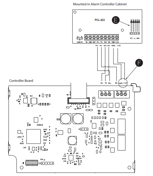
The PCL-422 will be connected to the DSC Neo panel using the included harness which will need to be connected to PCLINK2. Do not use PCLINK1 as this will not work. On the panel, the red of the harness will be on the right side. On the PCL-422, the red of the harness will be on the bottom.
Verify Installer Code to Activate Alarm.com Module
Alarms and other signals will not be sent to Alarm.com until the installer code is verified. To activate the account, perform the following steps:
- Enter programming by pressing *8 + Installer Code
- Press # to exit programming