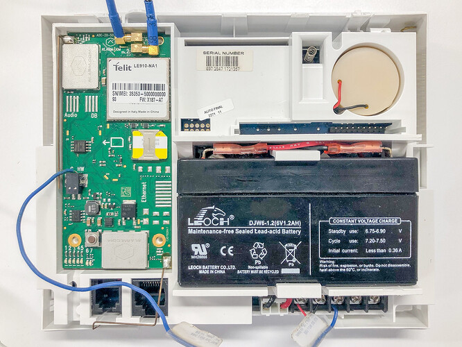
Requirements
- Depending on the firmware version of the module, a separate Image Sensor daughterboard may need to be attached.
- For modules with version 146-185, an Image Sensor daughterboard must be attached for compatibility.
- For modules with version 187+, Image Sensor compatibility is built-in and a separate Image Sensor daughterboard is not required.
- The blue daughterboard alarm hardwire must be installed locally for the Image Sensor to trigger the system alarm.
Prepare module for Image Sensor enrollment
- Verify the blue hard wire is connected properly to enable local alarm activations.
- Using a module with firmware version 187+, insert the blue alarm wire in the side of the cellular module labeled HW to connect to the HW2 IN (terminal 3) slot on the Simon XT panel.
Note: Modules with firmware version 187+ have the Image Sensor radio built-in to it, so no daughterboard installation is required if using that module version.
- Using a module with firmware version 146-185, insert the blue alarm wire from the HW hardwire output located on the daughterboard (use HW , do not use C ) to connect to the HW2 IN (terminal 3) slot on the Simon XT panel.
- Once an Image Sensor has been enrolled into the Simon XT panel, a hardwire zone is automatically programmed as Sensor 39: ISHW.
- To ensure alarms are tripped properly on Image Sensors according to their enrolled group, the hardwire sensor group is automatically configured. Do not alter the sensor group of Sensor 39 ISHW.
To locally enroll an Image Sensor using the Interlogix Simon XT:
For smoothest installation, enroll one Image Sensor at a time. Insert batteries only after initiating learn mode at the panel.
- Begin with the batteries removed from the Image Sensor.
- Put the panel into add mode using the keypad.
- Go to the home screen.
- Scroll to System Programming, then press [ OK].
- Enter the installer code (default is 4321), then press [ OK].
- Scroll to Interactive Services, then press [ OK].
- Scroll to Image Sensor Setup, then press [ OK].
- Scroll to Image Sensor Learn Mode, then press [ OK]. The screen should display Power up or set I. S. Mode.
- Insert the batteries into the Image Sensor.
- For an Image Sensor Version 3 (i.e., 300-LP), the LED on the Image Sensor changes from blinking red to solid red to blinking yellow. This indicates the Image Sensor is in learn mode. There is no indication of learn mode for the Image Sensor Version 1 or 2 (i.e., 221-LP).
- Wait approximately 20 seconds for the control panel screen to display I.S. [x] Added as Sensor [y].
- For an Image Sensor Version 3, the LED on the Image Sensor turns solid yellow indicating that it has successfully found the panel.
- For an Image Sensor Version 1 or 2, the LED on the sensor turns solid for about 5 seconds indicating that it has successfully found the panel.
- Exit installer programming.
- For Image Sensors Version 3, the Image Sensor LED alternates between green and yellow while the customer’s device list is updated with Alarm.com. The LED turns solid green when the Image Sensor has been successfully added to the customer’s account.
Note: If the Image Sensor is moved (tampered) after the LED has turned solid green, the Image Sensor enters test mode for 3 minutes indicated by a red LED when motion is detected. The mounting portion of the installation may be continued with while the Image Sensor is in test mode.
-
Perform another panel communication test. This ensures that Alarm.com receives the updated device equipment list and speed up the sensor initialization process.
-
After enrollment, be sure to keep the sensor and panel powered so the sensor can complete an initialization process with the Alarm.com Network Operations Center. This process takes several minutes. Images cannot be captured until initialization is complete.
