Pre-installation checklist
- Dome camera (included)
- PoE network switch or injector
- Broadband router with available Ethernet port
- Ethernet cable (Cat5e or better)
- Computer or mobile device with Internet access
- Username and password for the Alarm.com account to which you will add the camera
- Mounting hardware and tools (drill, screwdriver, included wrench or T10 driver)
- Dedicated gasket-piercing tool (included)
- AO-15 cable (optional, required for audio line level input/output and Digital IO)
In the box
- ADC-VC8498PA
- Mounting template
- L-shaped wrench
- Gasket-piercing tool
- Wall anchors & screws (x4)
Installation and enrollment
Note the ADC-VC8498PA does not include a built-in speaker. An external analog speaker is required for Two-Way Audio functionality. For steps to install an AO-15 cable to allow for external speaker installation, proceed to External audio connections (optional)
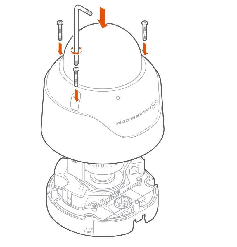
Remove the cowl
Note: The camera’s cowl must be removed in order to mount the device.
-
Use the included wrench or a T10 driver to loosen and remove the screws securing the top cover.
-
Remove the desiccant packet that was included inside the camera’s housing for transport.
-
Retain the screws and cover for re-installation after cable routing and mounting.
Mount the camera
Note: Before mounting, remove the protective plastic lens cover from the camera to ensure a clear image.
-
Use the included drill template to mark holes for the mounting screws and cable pass-through.
-
Install anchors as needed for your mounting surface.
-
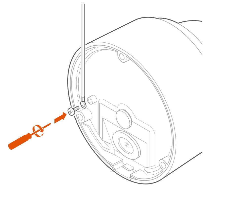
Secure the camera base using the supplied screws.
-
If grounding is required, connect the ground wire to an approved earth ground per code.
-
Determine whether the AO-15 cable will be used for the installation. Connect the Ethernet cable to the camera’s RJ45 port using the appropriate set of steps below to ensure a secure fit.
Gasket piercing and Ethernet cable routing
The AO-15 cable is required in order to use external audio line-level input/output.
Note: For outdoor/wet installations, assemble all cable glands and weather caps as specified. Wrap connectors with waterproof tape for extra protection.
NOT using the AO-15 cable
-
Attach the RJ45 connector to the included gasket-piercing tool.
-
Using the tool with attached RJ45, pierce directly through the center of the original rubber gasket. This ensures a snug fit and a weatherproof seal.
-
Feed the Ethernet cable fully through the pierced gasket.
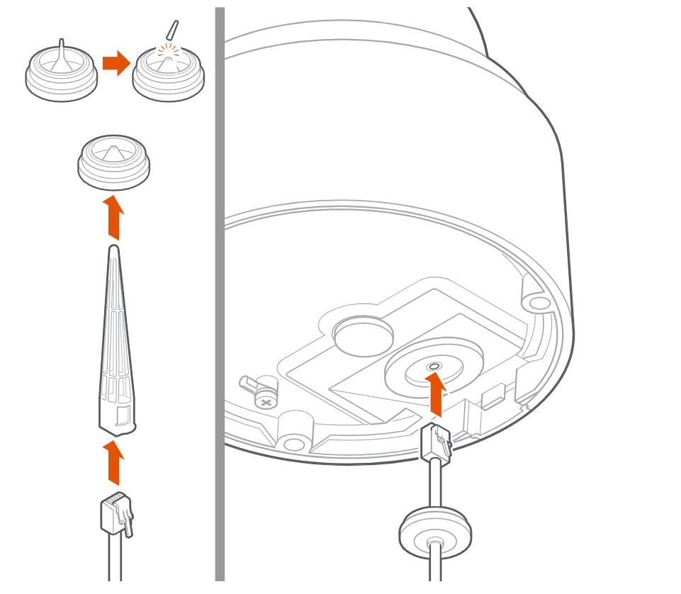
Important : Before proceeding, verify that the gasket is fully seated on both sides of the metal enclosure to ensure a complete weatherproof seal.
Using the AO-15 cable
- The AO-15 cable includes a replacement gasket designed for the bundle.
- Do not pierce or use the original gasket.
- Install the replacement gasket supplied with the AO-15 and route both the AO-15 and Ethernet cables as directed.
Important: Before proceeding, verify that the AO-15 gasket is fully seated on both sides of the metal enclosure to ensure a complete weatherproof seal.
External audio connections (optional)
Notice : Although the ADC-VACC-AO-015 cable includes wires for Digital I/O connections, these connections are not currently supported.
Note : The AO-15 cable and gasket should be installed during initial setup if these features are desired, as retrofitting may require dismounting the camera.
- If installing external audio line-level input/output, connect the AO-15 cable to the designated port during initial installation. Refer to the color-coded diagram provided with the AO-15 for wiring details.
- Unused AO-15 wires should be insulated to avoid shorts.
Re-install the cowl
Once cable routing is complete, re-install the cowl to finish physical installation.
Caution: When re-installing the cowl, re-tighten the cover screws to 6 kg-inch (0.59 Nm) using the included wrench or a T10 driver. Do not under- or over-tighten, as improper torque can lead to water ingress.
Enroll the camera to the Alarm.com account
Alarm.com Mobile app installation wizard
- Log in to the app. You will need the username and password of the account to log in.
- Tap Menu
- Tap Add Device. If you do not see the Add Device option, use the Ethernet mode instructions below to complete installation.
- Tap Video Camera.
- Tap VC8498PA.
- Follow the on-screen instructions.
Ethernet mode
Note: Complete these steps prior to installing the camera in its final location.
- Feed the Ethernet cable through the cable gland and connect it to the camera’s RJ45 port.
- Connect the other end of the Ethernet cable to the PoE switch or injector.
- Wait 2 minutes for the camera to boot up and connect to the Internet. The LED will be solid green when this process is complete.
- Add the device to the account by either selecting the account in the MobileTech app or by using a web browser and entering the following web address: www.alarm.com/addcamera. You will need the customer’s username and password.
- Select the camera from the video device list or enter its MAC address to begin adding the camera. The camera’s MAC address is located on the bottom of the device or on the packaging.
- Follow the on-screen instructions to finish adding the camera.
Configure the audio input/output settings
Users can enable or disable the camera’s audio input and output, select the input device (i.e., the built-in microphone or an external line-in microphone), and adjust the gain for a line-in microphone using the Alarm.com mobile app or website.
- Log in to Alarm.com
- Click Video.
- Click Settings.
- Select the desired video device.
- Click Audio.
- In Audio Settings:
- Click the Audio Input/Output toggle switch to enable or disable both audio input and output together as desired.
- To configure the audio input only, in Audio Input select Disabled , Built-in Microphone , or Line-In
- To configure the audio output only, in Audio Output select Disabled or Line-Out
- Use the Line-In Gain slider to adjust the gain for Line-in audio inputs.
- Click Save.
LED reference
| LED pattern | Description |
|---|---|
| Not illuminated | Power off |
| Solid green | Connected to Alarm.com |
| Blinking green | Local network connection |
| Solid red | No local or Internet connection |
| Blinking red | Power on, camera booting |
| Blinking yellow | Power cycling (Hold Reset button for 9-12 seconds) |
| Blinking green and red | Reverting to factory default settings (Hold Reset button for 12-15 seconds) |
Troubleshooting
- If the camera fails to connect to the network or enroll to the account, power cycle the device and try again.
- If issues persist, reset the camera to factory defaults. Press and hold the Reset button for 12-15 seconds until the LED is flashing green and red, then release the button.
Important: If the camera was previously installed to a different Alarm.com account, it will need to be deleted from that account before it can be installed again.