Pre-Installation Checklist
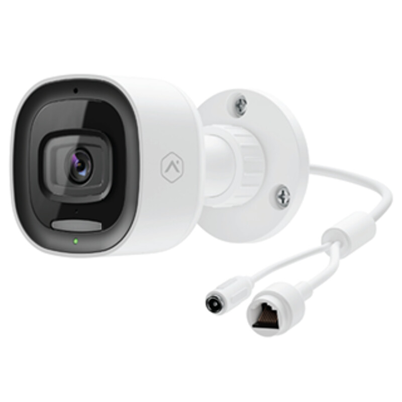
- ADC-VC730P camera (included)
- PoE switch
- ADC-V730 AC power adapter (required for non-PoE connections) (sold separately)
- An Ethernet / Cat5e cable
- Router with broadband Internet connection (Cable, DSL, or Fiber Optic) and an open Ethernet port
- A computer or mobile device with Internet access
- Username and password for the Alarm.com account to which the camera is added
In the box
- ADC-VC730P camera
- Installation sheet with QR code and drill template
- Wall anchors & screws (3)
- Rubber plug
- A rubber plug has been included with the ADC-VC730P at the base of the mount. This rubber plug should only be used if the device is being mounted directly over a hole in the wall. The rubber plug will provide a seal to prevent water from entering the hole in the wall behind the camera. In all other installations, please remove the rubber plug. Removing the rubber plug will allow you to route the power cable through the mouse hole without bending or breaking the cable.
Overview
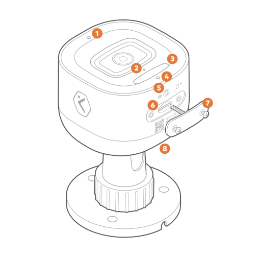
1 Ambient Light Sensor
2 Microphone
3 Spotlight
4 Status LED
5 Reset Button
6 SD Card Slot
7 SD Card Door
8 Speaker
Installation
Enroll the camera to the Alarm.com account
Ethernet Mode
- Feed the Ethernet cable through the cable gland and connect it to the camera’s RJ45 port.
- Connect the other end of the Ethernet cable to the PoE switch.
- Wait 2 minutes for the camera to boot up and connect to the Internet. The LED will be solid green when this process is complete.
- Add the device to the account by entering the following web address: www.alarm.com/addcamera. You will need the customer’s username and password. For more information about adding a camera to an account, see Enroll the video device to the customer account.
- Select the camera from the video device list or enter its MAC address to begin adding the camera. The camera’s MAC address is located on the bottom of the device or on the packaging.
- Follow the on-screen instructions to finish adding the camera.
You can now power down the camera and install it in its final location using the included hardware.
Physical installation
Verify there are no obstructions near the camera’s installation location. Obstructions close to the camera’s lens can lead to poor night vision performance.
To install the ADC-VC730P in its final location:
If the ADC-VC730P will be using an AC power adapter instead of a PoE switch, the ADC-V730 power adapter is required.
-
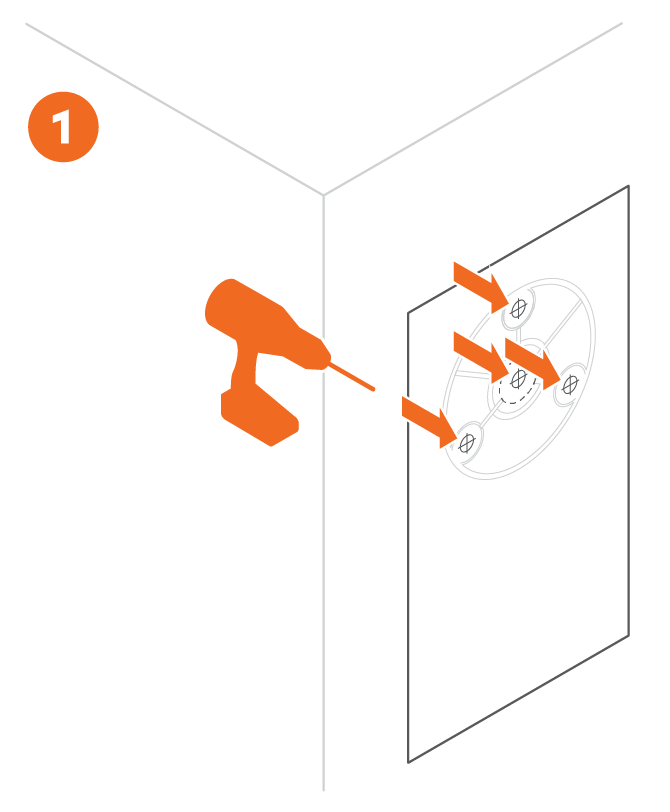
Use the included drill template to mark the desired location of the holes for the Ethernet/power cable and mounting screws. Drill a 1/2” hole in the center of the template for the Ethernet/power cable. If mounting to drywall, drill three 9/32” holes and insert the included M5 wall anchors. If mounting to a solid surface (e.g., wood), drill three 1/8” pilot holes.
-
Mount the device to a flat surface (e.g., a wall or ceiling) 8 feet or more above the ground.
To mount the ADC-VC730P when routing the Ethernet/power cable through the wall:
- Install the rubber plug over the hole for the Ethernet/power cable.
- Connect the device to its power cabling:
- If using an Ethernet cable for power, connect the cable to a PoE switch. Insert the Ethernet cable into the center hole from the mounting template.
- If using an AC power adaptor for power, connect the 12 VDC connector to an unplugged 12 VDC adapter. Insert the power cable into the center hole from the mounting template.
- Line up the camera with the three holes created in step 1. Use the included ST4.8 x 32mm self-tapping screws to fasten the camera to the mounting surface (#10 drywall screws or 3/16" Tapcon screws are also acceptable).
To mount the ADC-VC730P when routing the Ethernet/power cable along the wall:
- Remove the rubber plug from the power cord.
- Connect the device to its power cabling:
- If using an Ethernet cable for power, connect the cable to a PoE switch. Insert the Ethernet cable into the center hole from the mounting template.
- If using an AC power adaptor for power, connect the 12 VDC connector to an unplugged 12 VDC adapter. Insert the power cable into the center hole from the mounting template.
- Line up the camera with the three holes created in step 1. Use the included ST4.8 x 32mm self-tapping screws to fasten the camera to the mounting surface (#10 drywall screws or 3/16" Tapcon screws are also acceptable). Route the cable through the cut-out in the mounting plate.
LED reference guide
| LED pattern | Description |
|---|---|
| Off | Power off |
| Solid green | Connected to Alarm.com |
| Blinking green | Local network connection |
| Blinking red | Power on, camera booting |
| Solid red | No local or internet connection |
| Blinking white | Bluetooth and Wi-Fi Access Point modes (press and hold the button for 3-6 seconds) |
| Blinking blue | WPS mode (press and hold button for 6-9 seconds) |
| Blinking yellow | Power cycling (press and hold button for 9-12 seconds) |
| Blinking red and green | Reverting to factory default settings (press and hold the button for 12-15 seconds) |
| Blinking green and blue | Firmware updating |
Troubleshooting
- If the camera was previously installed on a different Alarm.com account, it will need to be deleted before it can be installed again.
- If you have issues connecting the camera to the account, power cycle the camera and try again.
Factory Reset the ADC-VC730P
Resetting a video device to its factory defaults removes all programming and memory from the device.
Important: Wait at least 2 minutes for the video device to power on fully before performing the following procedure. The factory reset might fail if the device is still powering on.
-
Press and hold the WPS/Reset button until the LED is flashing green and red (about 12 seconds), then release the button. Button is located in front of the SD card door on the bottom of the device.
-
The camera will reboot to factory default.
Once a video device has been reset, it is normal for the LED to turn off momentarily. It is best to leave the video device plugged into power and undisturbed for 2 minutes after performing the factory reset.