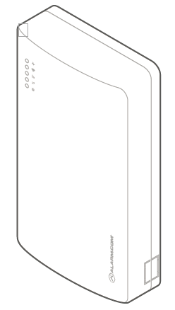
Alarm.com Dual-Path System Enhancement Module (SEM) is the most cost-effective and comprehensive solution to migrate compatible DSC PowerSerie PC1616, PC1832, and PC 1864 panels to Alarm.com. The Dual-Path SEM supports the 4G LTE cellular network and optional Broadband Ethernet. This ensures the longest life cycle with the most secure and reliable service.
Take inventory of all peripheral devices (wireless receivers, zone expanders, keypads, power supplies, etc.) wired to the system.
Inspect peripheral device wiring to verify there are no loose ends or intermittent connections between the device and system.
Note: The presence of peripheral device issues can often cause the SEM installation process to take longer than expected.
Verify all peripheral devices are supervised by the panel. To verify peripheral devices are supervised by the panel:
A. Press [*][8].
B. Enter the installer code.
C. Press [903].
Reset supervision if necessary. To reset supervision:
A. Press [*][8].
B. Enter the installer code.
C. Press [902].
Disarm and power down the panel
Verify the panel is disarmed and clear of any alarms, troubles, or system faults.
If you do not know the current installer code, check the installer code at the panel before powering down the panel.
Then remove AC power and disconnect the backup battery to completely power down the system.
After powering down the system:
Remove third party communication
If there are any third-party communicators installed or a POTS line connected to the panel, remove them.
The SEM is not compatible with POTS, IP/GSM devices, or other third-party communicators. Therefore, the SEM should be the only communication device installed for alarm signaling to the monitoring station.
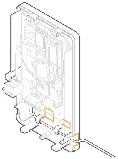
Evaluate how the wiring cables will be routed from the SEM to the panel.
Remove the snap-off plastics. There are two routing options available: the side of the enclosure for side routing or the rear of the enclosure for wall routing.
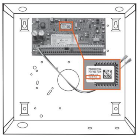
Verify the wiring of the primary antenna, diversity antenna, and ethernet dongle are routed correctly. NOTE: The Cat-M variant (indicated by the ME910 Telit radio) only requires the primary antenna.
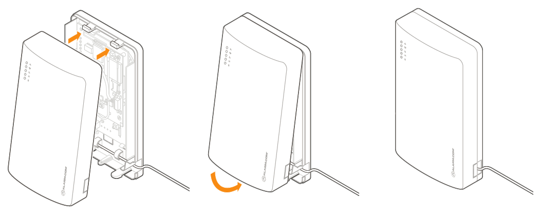
Press in on the thumb tabs located at the bottom of the enclosure, then swing up the top half of the enclosure cover to expose the internal components.
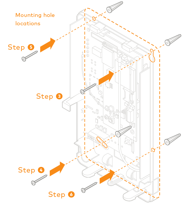
Place the SEM enclosure backplate against the wall at the desired mounting location and mark the four mounting holes.
Using the provided mounting screws and wall anchors (if needed), place the first mounting screw through the top-right enclosure hole. This screw will be used to hang the SEM from the wall while mounting and should not be tightened until the last step.
Place the second mounting screw through the bottom-left mounting hole. This screw is used to level the enclosure on the wall and should not be tightened until the last step. A standard leveling device may be used to ensure the unit is level.
Place the third mounting screw through the top-left enclosure hole. This screw should be tightened fully against the unit and wall before moving to the next step.
Place the final mounting screw through the bottom-right enclosure hole. This screw should be tightened fully against the unit and wall before moving to the next step.
Important : This screw is critical for the wall tamper functionality and should not be overlooked.
Tighten the first two mounting screws fully to the unit and wall to complete the mounting process.
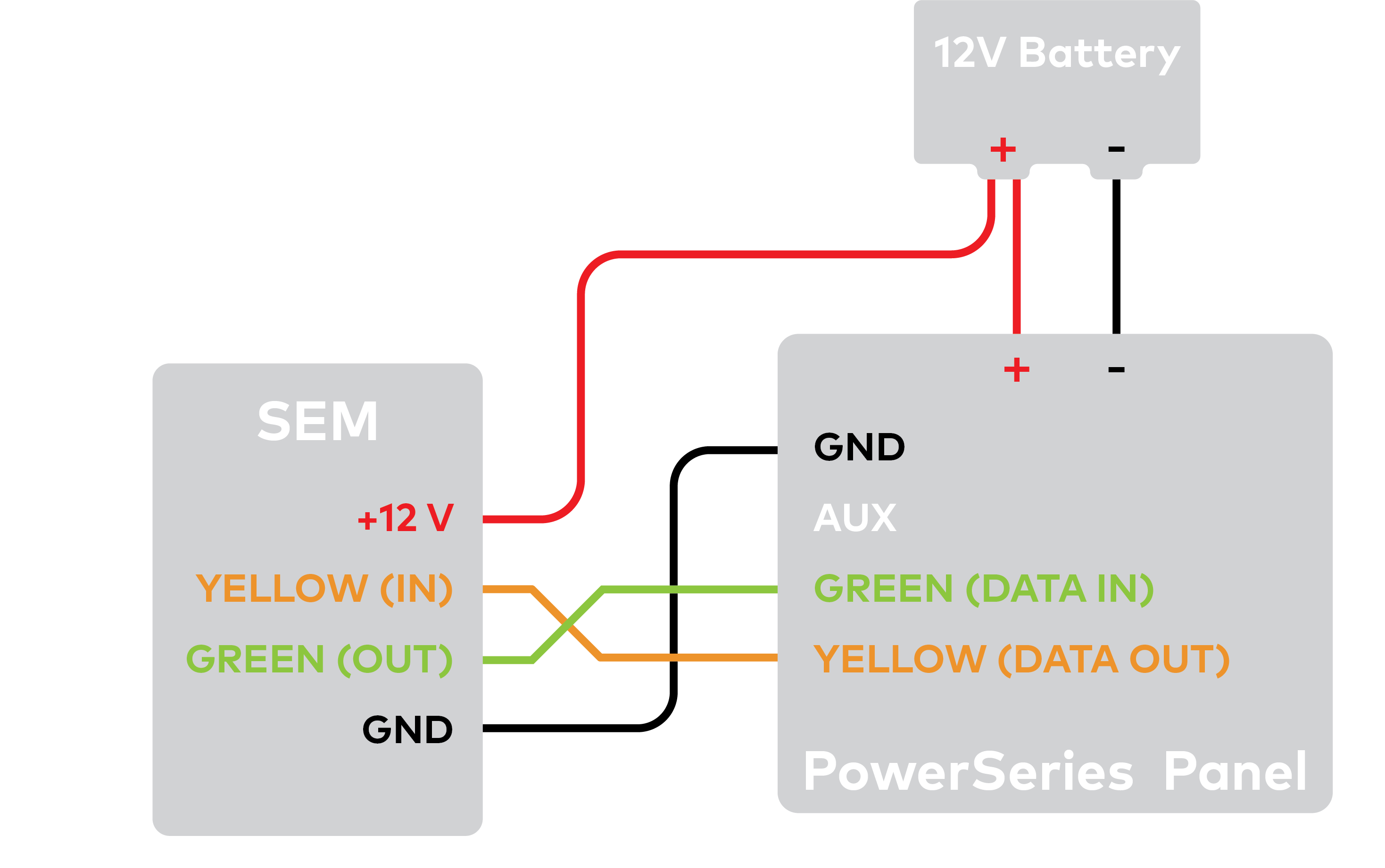
Connect the yellow/green data cables and red/black power supply cables to the designated locations at the SEM and panel.
Connect an Ethernet cable to the pre-installed Ethernet jack to utilize dual-path communication.
Remove the snap-off plastics from the enclosure side at the desired locations, then route the cables around the internal strain relief walls and out the side of the enclosure.
Before completing the mounting, verify the wiring connections are secure and all internal components are in their proper location.
Then close the enclosure by sliding the cover into the mounting points at the top of the enclosure base and then swinging down the cover to snap the thumb tabs into place.
Zone scan
Connect the backup battery and restore AC power to the panel. For the SEM to interact with the existing zones on the system, it must read them from the PowerSeries panel. The SEM does a zone scan to read this information.
The zone scan automatically begins within one minute after the panel is powered up and should take between 5 and 15 minutes, depending on the number of partitions and zones on the system. Do not touch the panel, keypad, or SEM at this time.
The zone scan is complete when the green and yellow lights on the keypad remain solid. If you press any buttons on the keypad during the zone scan, the message System unavailable displays on the screen. The date and time shows on the screen when the zone scan is complete.
Important: If the system was previously communicating over a phone line, we recommend Disabling Telco Line Monitoring (Section 015, Option 7) and Removing the Phone Numbers (Section 301-303).
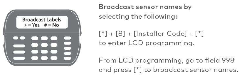
Broadcast sensor names
For the SEM to be able to read the sensor names stored on the panel and display them on Alarm.com, you must broadcast the sensor names stored on the keypads. This should be done for every install with an LCD keypad and is necessary even if there is only one keypad on the system.
Before completing the installation, verify that the SEM is fully in sync with the panel and communicating with Alarm.com by verifying:
The correct devices are present on the account equipment list in Alarm.com
2 You can view all user codes in the Alarm.com app or Website, and the correct users are reported when arming or disarming at the panel.
All alarms are reported correctly to Alarm.com and the monitoring station.
For the SEM to communicate with the panel and report all alarms, certain panel settings must be set at the panel. These settings are automatically changed during installation, so no further action is required by the installer.
Edit master code
Section 015, option 6 is disabled. This setting is required for SEM to change the master code via the User Programming *5 menu.
Arm/Disarm with Trouble
Section 021, option 8 is disabled. This setting is required for SEM to arm the panel when a trouble is active. This setting is available on select DSC panel versions.
Swinger Shutdown
Section 1xy, option 6 is enabled or disabled based on the default zone attributes (i.e., section 101, option 6 is enabled for zones programmed as group 01 Delay 1, but disabled for zones programmed as group 08 24 HR Fire). This setting is required for SEM to support the swinger shutdown feature.
Transmission Delay
Section 1xy, option 7 is disabled. This setting is required for SEM to report zone alarms immediately.
Report codes
Sections 320-349 do not determine or impact event reporting on Alarm.com.
Important: All monitoring station forwarding settings should be set up via Alarm.com Monitoring Settings.
The Trouble LED flashes 1 to 8 times in a four-second interval to indicate specific error conditions.
Flash pattern
Description
1
The Alarm.com module cannot communicate with the panel. Perform a power cycle on the panel.
2 then 4
The Alarm.com module provisioning process could not be completed. Power cycle the system.
2 then 5
The Alarm.com module provisioning process could not be completed because the module is currently roaming off the carrier’s primary network.
3
The Alarm.com module is trying to register on the cellular network. If it persists for more than a few minutes, the module is having problems registering. Check L4 for signal level. If signal level is lower than 2 bars, change the panel’s location or use a remote antenna option.
4
The Alarm.com module is registered on the cellular network but could not connect with Alarm.com.
5
The radio on the module is not working correctly. If this persists for more than a few minutes, the module may need to be replaced. This error is extremely rare, so please verify that the module is flashing 5 times.
6
This indicates an error only if it persists for more than a minute. Otherwise, it’s an indication that the module is resolving an unusual condition regarding communication with the cellular network.
7
The SEM is unable to access panel programming. Check the panel wiring and installer code.
8
If this error persists, the account may have been set up incorrectly. Check that the serial number being used matches the serial number used to create the account. If the serial numbers are the same,