Guys I’m updating from a Concord 4 to a new Qolsys panel and have a question on the Zones. All of the sensors tied to the panel are door / window sensors.
It appears the previous installer combined some of the individual zone wiring into a single zone. I’m guessing this is due to the limited number of zones on the C4 panel. For example, I’m guessing all the doors (3 of them) are tied to a single zone) Since the 16F has plenty of zones, is it safe (recommended even) to break these out into individual zones?
Also, the C4 installation already had resistors, do I need to swap out those resistors (re-resitorize?) with the resistors shipped with the 16F?
If you can identify the individual sensor circuit wires and break them off of the series circuit, you can of course turn those into individual zones. Usually on wired panels installers will combine windows especially, but it wouldn’t hurt to break them off.
On the new Hardwire 16F it is often much easier (and recommended) to replace all resistors with the 4.7kohm resistors which come with the Hardwire. By default the Hardwire 16F will look for 4.7kohm.
Optionally you could turn on EOL learning and learn them in using the existing resistors (IF they are between 1-10 kohm), however this can be a bigger struggle than just physically replacing the resistors, and if you run into an issue with resistance changing on a zone after learning it in you would need to reset the whole Hardwire 16F and start over.
Thanks Jason. Following your guidance I re-resistorized the sensors using the included resistors. I also went ahead and mapped each sensor to its own zone.
Follow up question… I have an internal siren, which I wired to the wiring diagram, but I also had a few stray wires that were mapped into the external siren on the concord 4. I don’t think I have an external siren, but I do have an external wired camera. Is there a chance that external siren wires are for powering the camera?
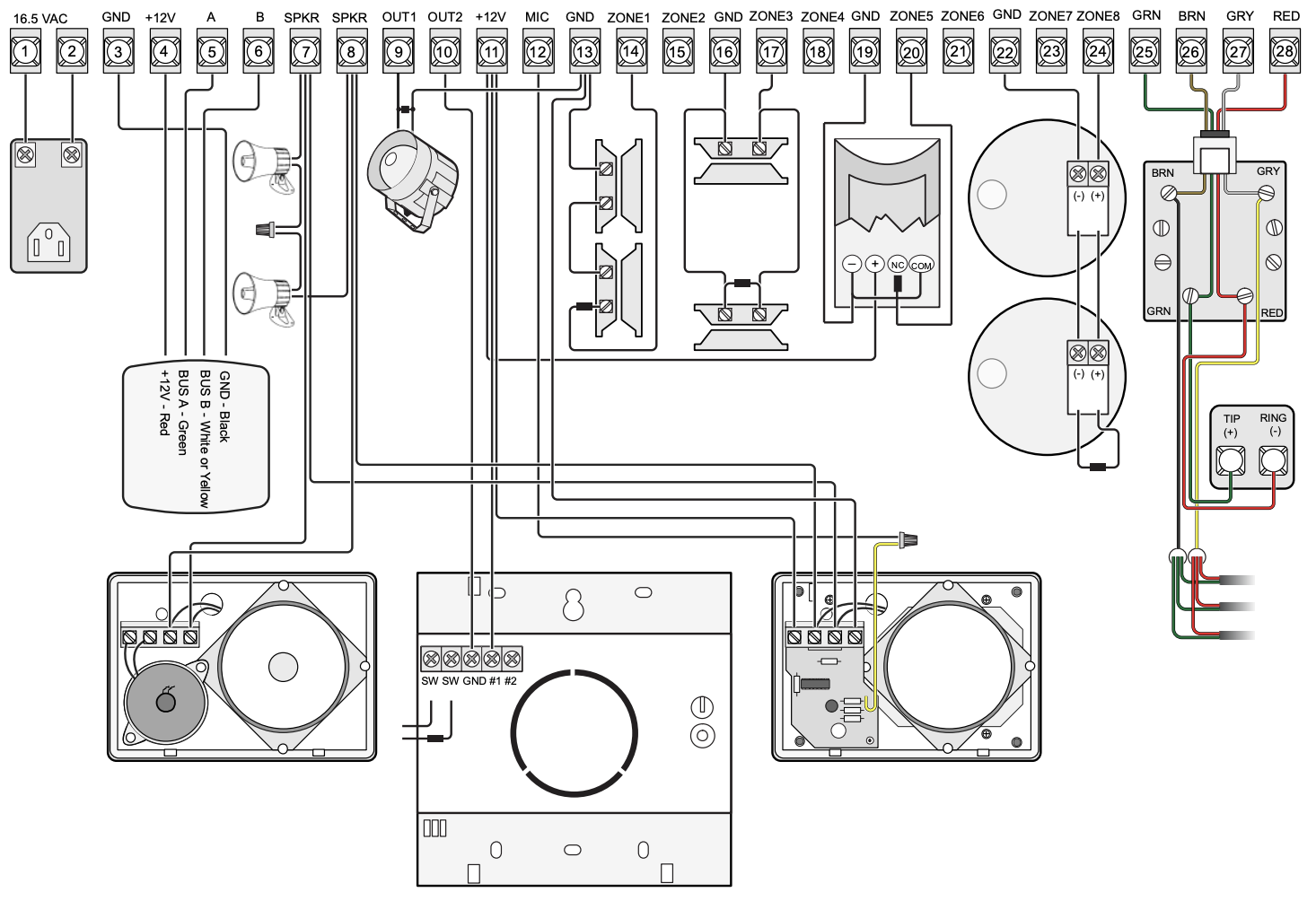
In the manual when it say interior (SPKR) vs exterior (OUT1) siren, the SPKR terminals are for connecting a speaker-type siren that takes an oscillating input signal and OUT1 is for connecting a piezo siren that takes a 12VDC input signal.
OUT1 can also be used for other things that take a 12VDC input signal such as a strobe light. Or if you have some kind of light that indicates when the system is armed, OUT1 could be powering that. I doubt OUT1 would be powering a camera because it’s only on in certain programmable conditions, like when the alarm is sounding or the system is armed.
If your siren was wired to the SPKR terminals on the concord then it won’t work with the Hardware 16-F. The 16-F only works with piezo sirens, like would be connected to the OUT1 terminal on the Concord 4. You could get a 12VDC speaker driver and add it to the speaker-siren you have or you could replace it with a piezo siren.
Thanks Roy. You guys really are great with support.
I must have an external alarm somewhere, but didn’t ID one in my assessment/inventory of the current system. For now, I’ll mark the wires and will set them aside.
I do think I have a piezo in the back hallway. It’s a SD 15W-ULF. Link
On the 16F, per the wiring diagram, I’ve mapped that into the Siren GND/Out with a jumper in Aux/In.
Let me know if that doesn’t sound right, otherwise thanks again for the help!
That makes sense. The one that was connected to OUT1 is the piezo and will work. It could be indoor or outdoor. If you had one connected to SPKR that’s just a speaker and won’t work with the 16-F.
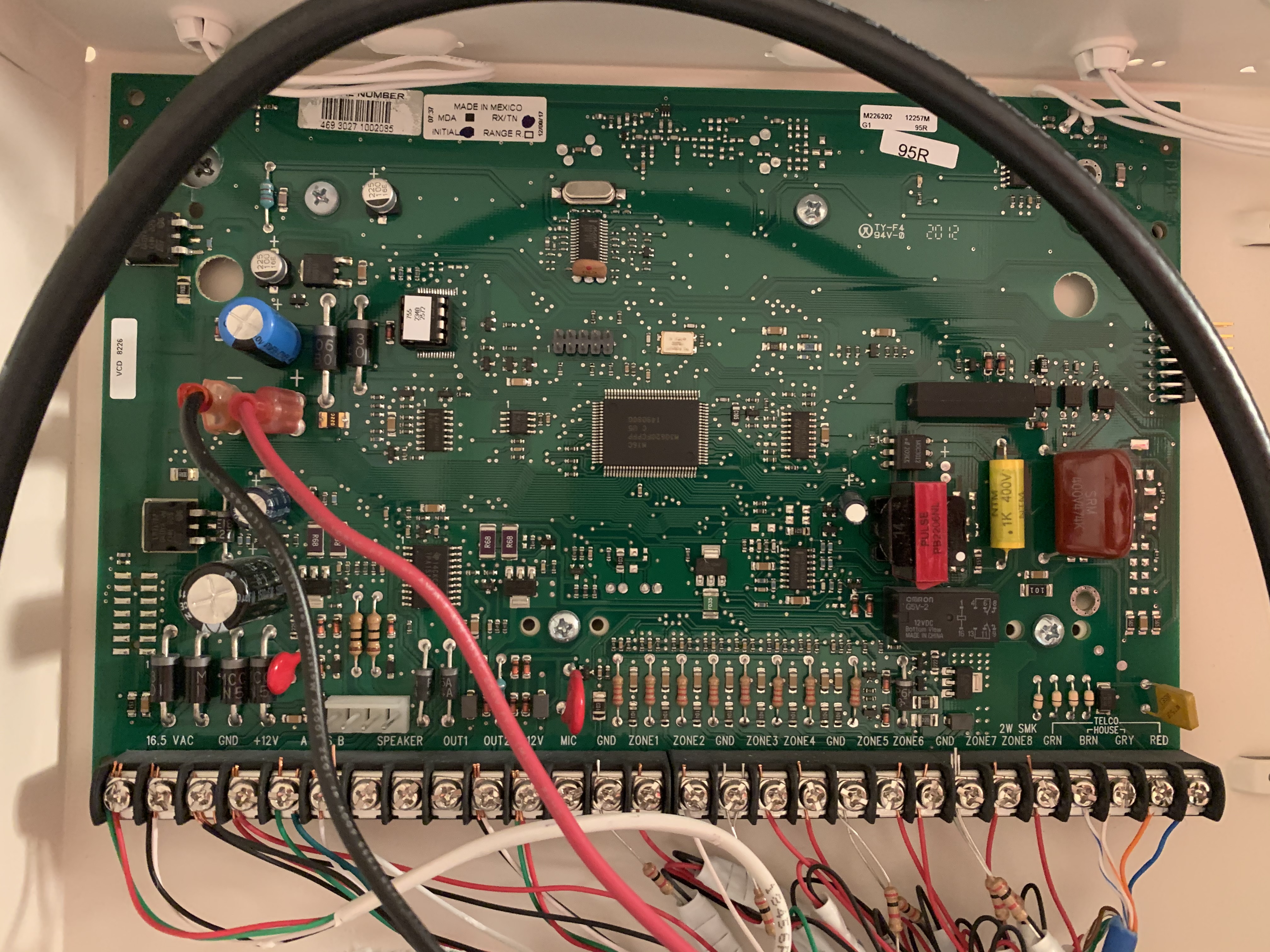
I recently purchased the Qolsys 2 panel and am also transitioning from a Concord 4. I will be using the Hardwire 16F for my hardwire sensors. Moving the sensors over seems to be straight forward to me (i.e., move Zone 1 wires from Concord 4 panel to the Zone 1 connections on the Hardwire 16F). However, similar to User99150, I am curious if I can move over the siren attached to the Concord 4 and, if so, how it wires to the Hardwire 16F as it does not seem straightforward to me based on the 16F installation instructions and how my Concord 4 is wired. Please see the pictures below for the 16F instructions and my Concord 4 panel. On my Concord 4 panel, it appears there is a black wire and a white wire run into terminal 10 (i.e. OUT2) and a red wire and green wire run into terminal 11 (i.e., 12V).
Can you please let me know if these four wires can run into my Hardwire 16F and if so how they should attach based on the instructions? Thanks!
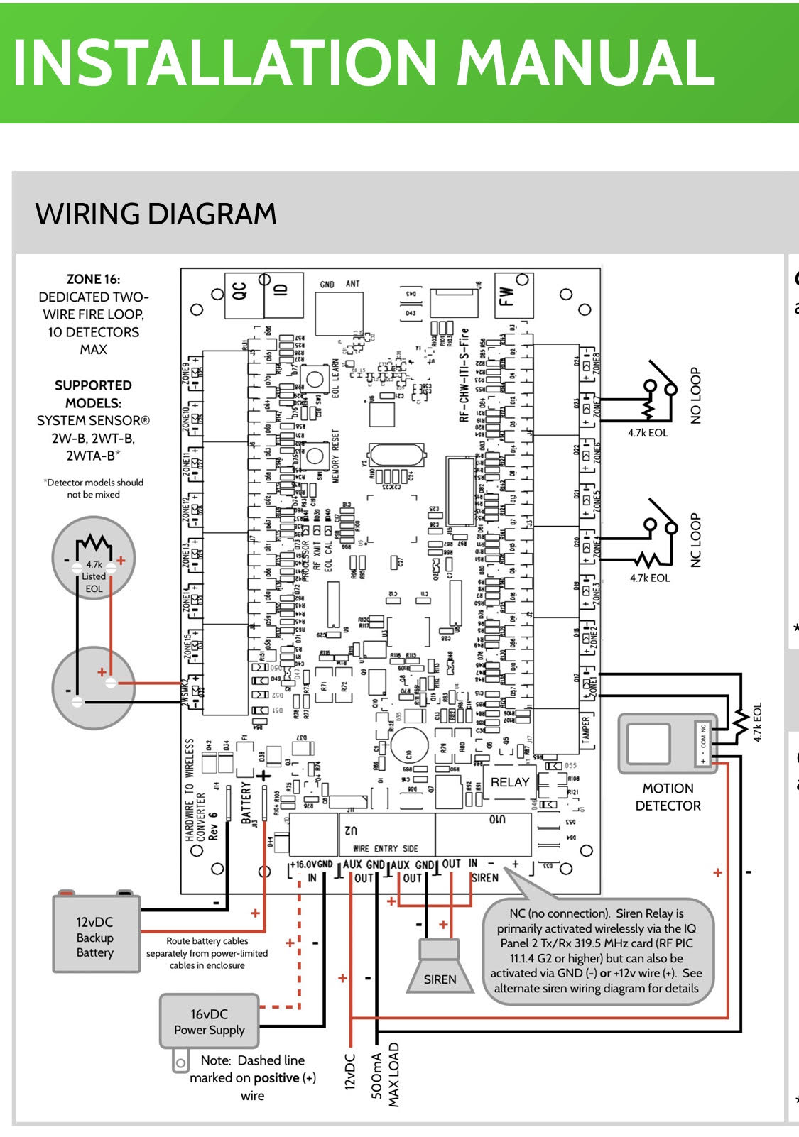
Looks like the Black and White are - and Red/Green are +. OUT2 is an open collector which closes to GND.
Connect Black and White to GND on the HW16F (where the - siren wire is shown attached).
Run a jumper wire between AUX and IN as shown in the diagram.
Connect Red and Green to OUT on the HW16F (where the + siren wire is shown attached).
This will rely on wireless activation of the siren relay and requires the Hardwire16F to be learned into the panel as a translator for supervision per the quick start guide.
Jason - thanks so much. One last question to close this out. Other than the wires attached to my Concord 4 panel at terminals 10 and 11 (i.e., the siren) and terminals 13 through 24 (i.e., my hardwire sensors) am I correct in that all the other wires will not need to be moved over to the HW16F or used in any way by my Qolsys system? Thanks!
That’s correct. The rest of the wires are AC transformer, BUS devices like Keypads, and the telephone lines for the old system. None of those are used with the Hardwire 16F
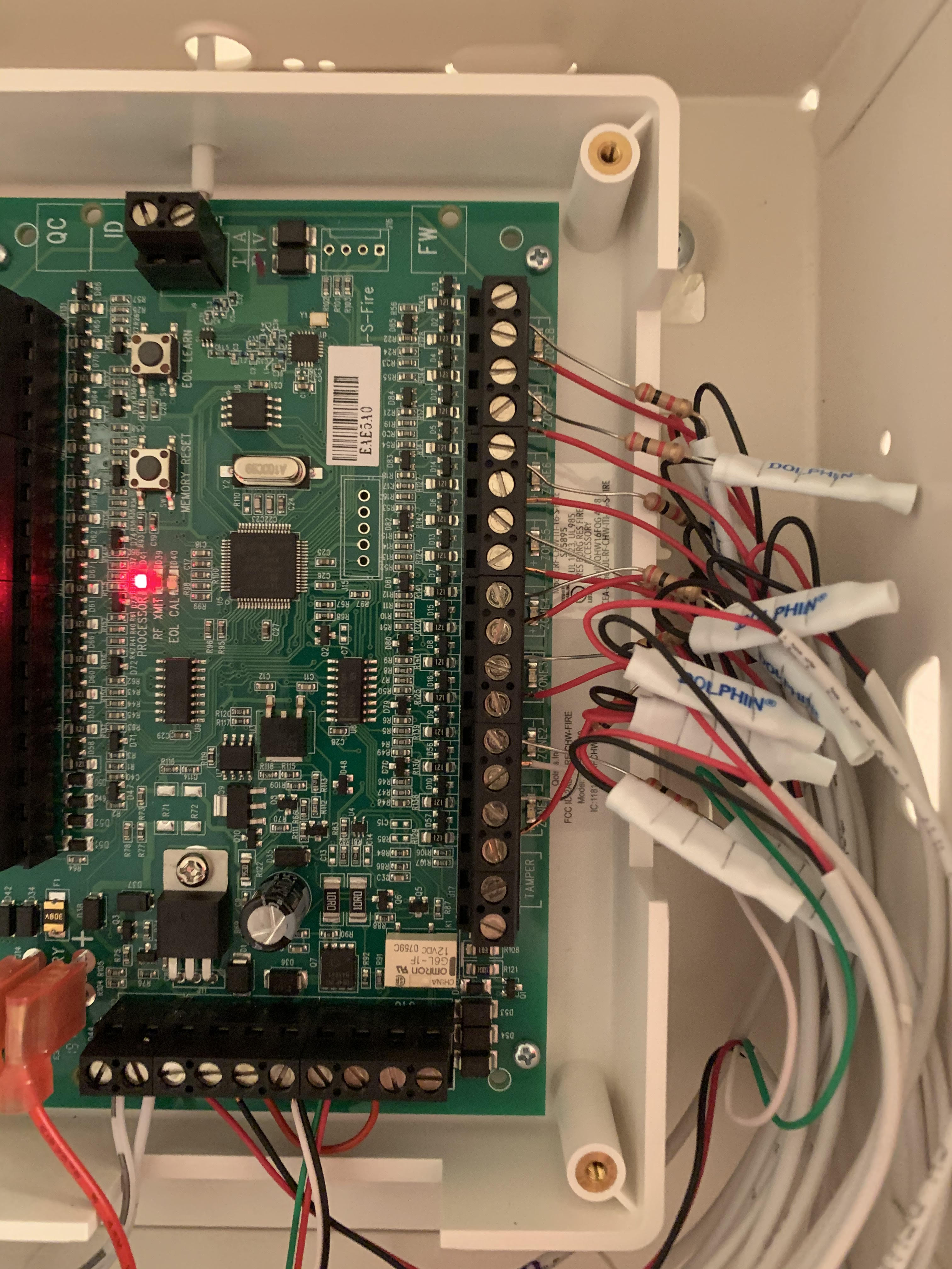
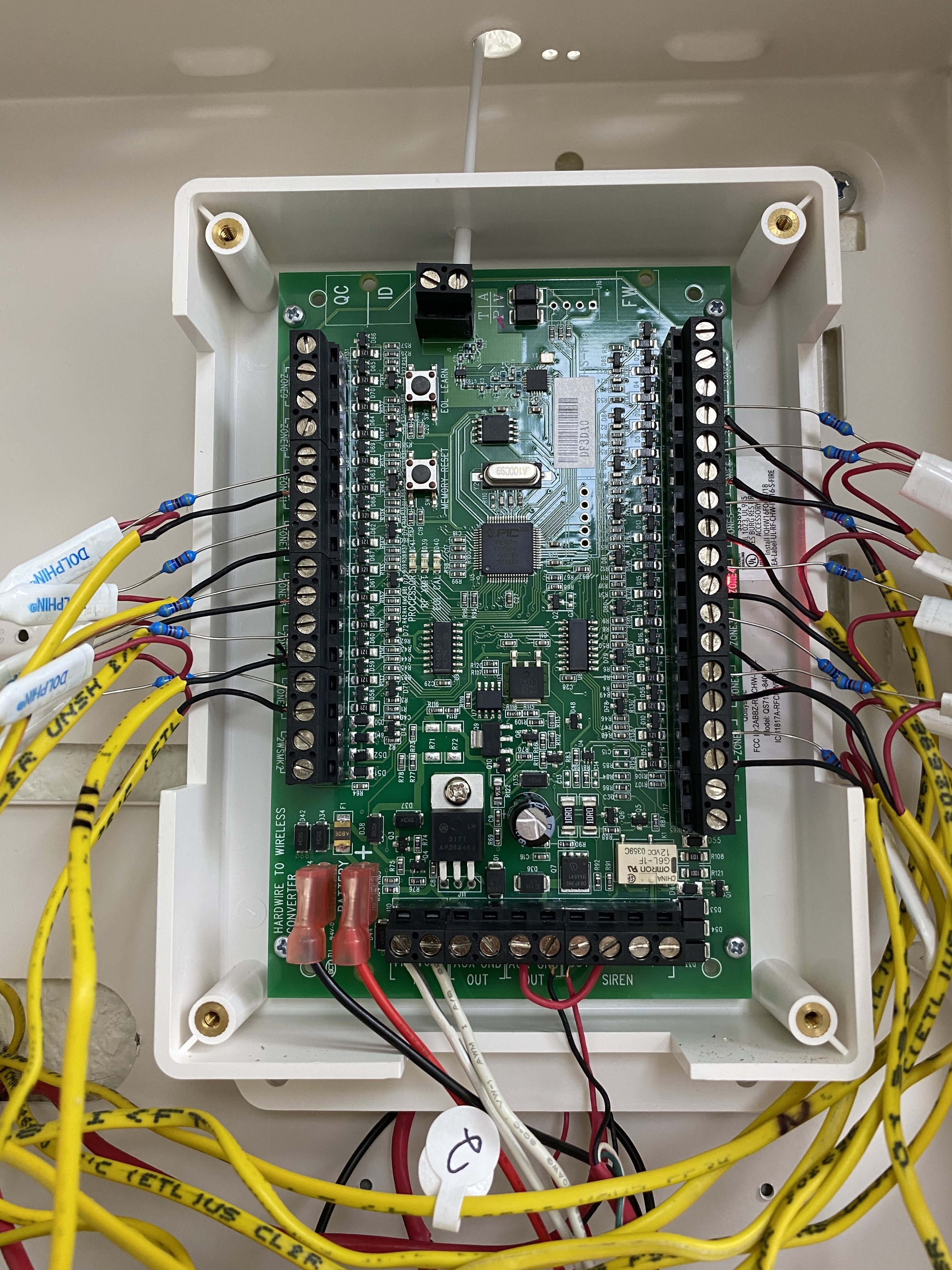
Jason - thanks so much. I attempted to do the install this weekend, but was not successful. I was able to wire the HW16F (see picture below), power it up and get it recognized and saved as a Hardwire Translator on my Qolsys 2 panel. However, I cannot get the Qolsys 2 to recoginize any sensors. I have followed the directions (i.e., turn on Auto Learn Sensor on panel, press EOL Learn on HW16F and ensure EOL CAL is lit and then trip sensors. However, I have tried multiple sensors on my system and none of them get recognized. Could I have wired something incorrectly? Is there a step I am missing? Any help would be appreciated. Thanks!
Are you still using the old resistors that were used with the Concord?
By default the HW16F will look for 4.7 kohm resistance on each circuit (the resistors included with the HW16F are 4.7 kohm.)
The HW16F can instead be set to learn in resistance of each circuit individually, but this can get complicated and I find it is generally easier and better to have universal 4.7kohm resistors and physically swap them out.
Thank you User99150 for the pic and Jason for the response. Appreciate it. I left the resistors on from the Concord system so perhaps they are not 4.7 kohm. Would rather not physically swap out the resistors just because I don’t have the tools or supplies to do so. That said, with a little help I could figure it out. Alternatively, do you have guidance on how to learn in the resistance of my current resistors?
Apologies, I forgot, on the latest Hardwire 16F versions it looks like the optional Resistor Modes have been removed. You must use 4.7kohm resistors. If you recently bought the HW16F it wouldn’t have that option.
A pair of pliers and some b-wire connectors or small wire nuts from the hardware store is all that is needed to swap them out.