Concord 4 DIY troubleshooting, unknown zones

I just switched to suretyDIY/ADC and am very pleased so far. As an added bonus(?), however, I’m discovering a number of issues with my Concord 4 system I was not aware of and would like to address the more important ones.

    Zone set-up:

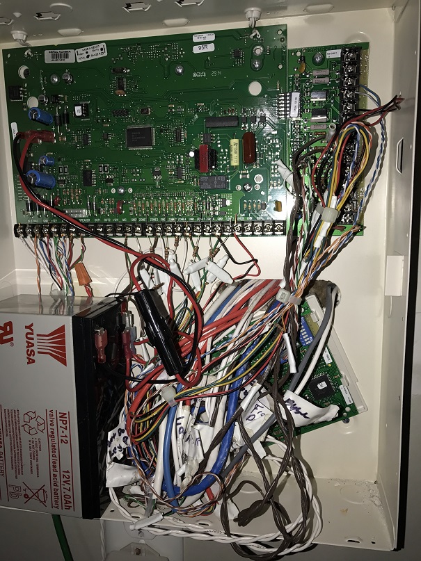
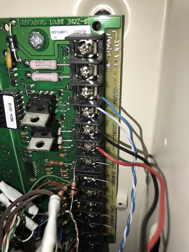
My panel consists of the main Concord 4 panel (8 HW zones), an expander snapcard (8 HW zones) and another expander (8 HW zones; 4 used). I can visually confirm 20 zone terminals are being used (8+8+4) in the panel. Please see attached photos. This matches the 20 HW zones my installer scribbled on a piece of paper 3 years ago. In addition, the installer had installed 3 RF zones (zones 21, 22, and 23), for a total of 23 zones in the system. Zone 21 was temporary and is not being used currently (and ADC didn’t pick it up in the sensor list).

For background, below is the zone information for the system.

[Removed]

    Problem #1: Basement Entrance Door (Zone 11)

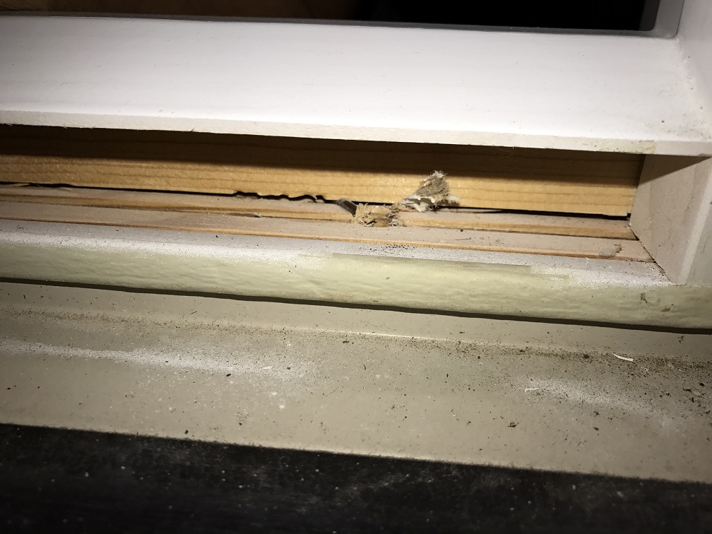
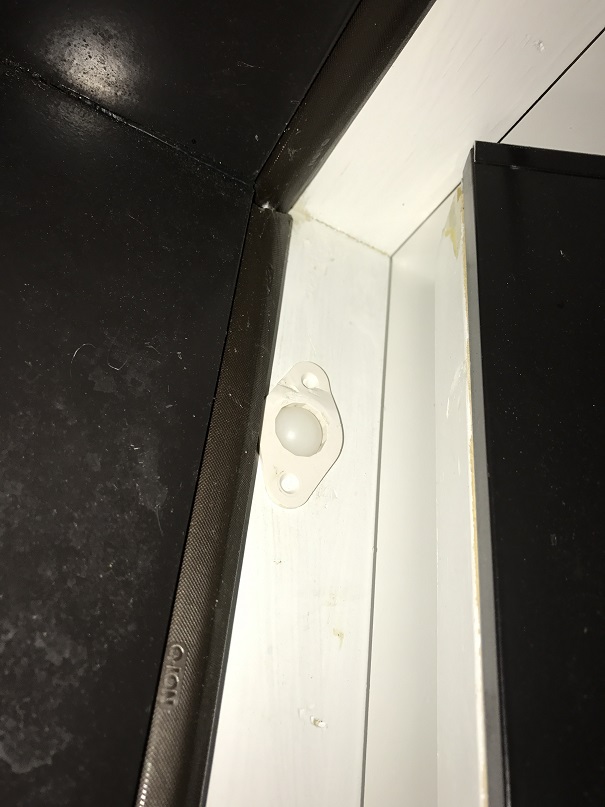
The system was installed during home construction, and the installer had temporarily used a wireless sensor for basement door (Zone 21) because the door was not installed when the alarm was put in place. A few months after we moved in, the installer came back, removed the wireless sensor, and installed a hardwired sensor on Zone 11. When I ran Sensor Test as part of the activation process with suretyDIY, the basement door (Zone 11) did not trip the alarm when I opened and closed several times. We almost never use this door and I did not know it was not working properly. Upon inspection, I learned that the sensor he used is the “plunger” type installed on the hinge side. (See pic.) I clicked on the roller button several times, and it seems the sensor is being detected by the panel (as per sensor activity log), but even that doesn’t seem consistent.

Questions:

  • What is the best course of action for me to have a reliable door sensor for Zone 11 (basement door)? Should I get a new plunger sensor? Should I go with a wireless sensor? Any recommendations?
  • If I install a new plunger sensor and it works, do I need to actively delete Zone 21, as it won’t be used?
    Problem #2: Unidentified zones 18, 19, 20

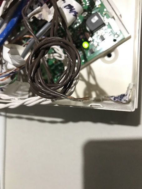
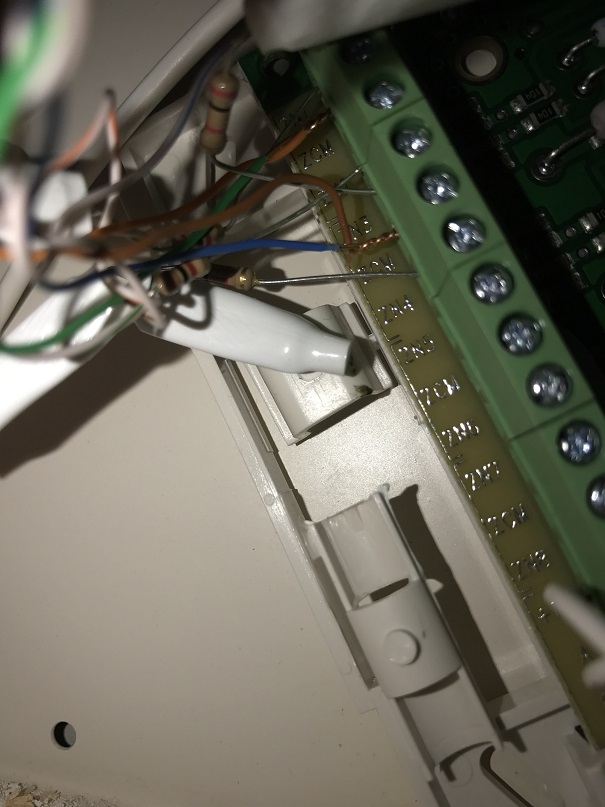
I tested all the doors and windows on the 1st floor and basement, and can’t understand which room these three zones are associated with. Zone text descriptions don’t help, as Master BR and all other bedrooms are on the 2nd floor and none of the windows on the 2nd floor have sensors installed. I looked at the terminals on the expansion panel and there are wires attached, but none of them are labeled and I can’t figure it out.

Questions:

  • Can you suggest anything I might be able to do to identify what these zones are for?
  • Should I just delete these three zones?
  • If I delete the unknown zones from panel memory, do I need to physically disconnect the wires from the panel terminals?
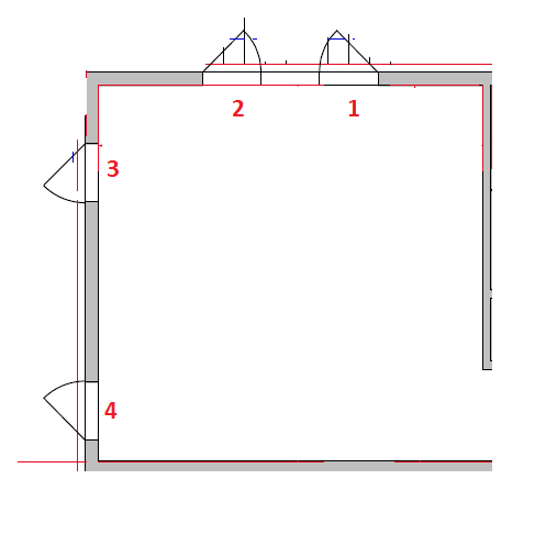
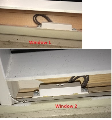
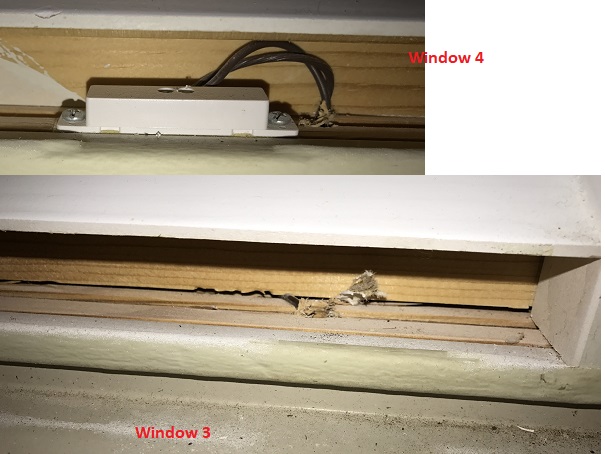
    Problem #3: A room has sensors, but panel doesn't detect

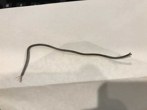
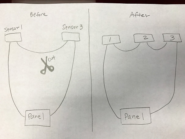
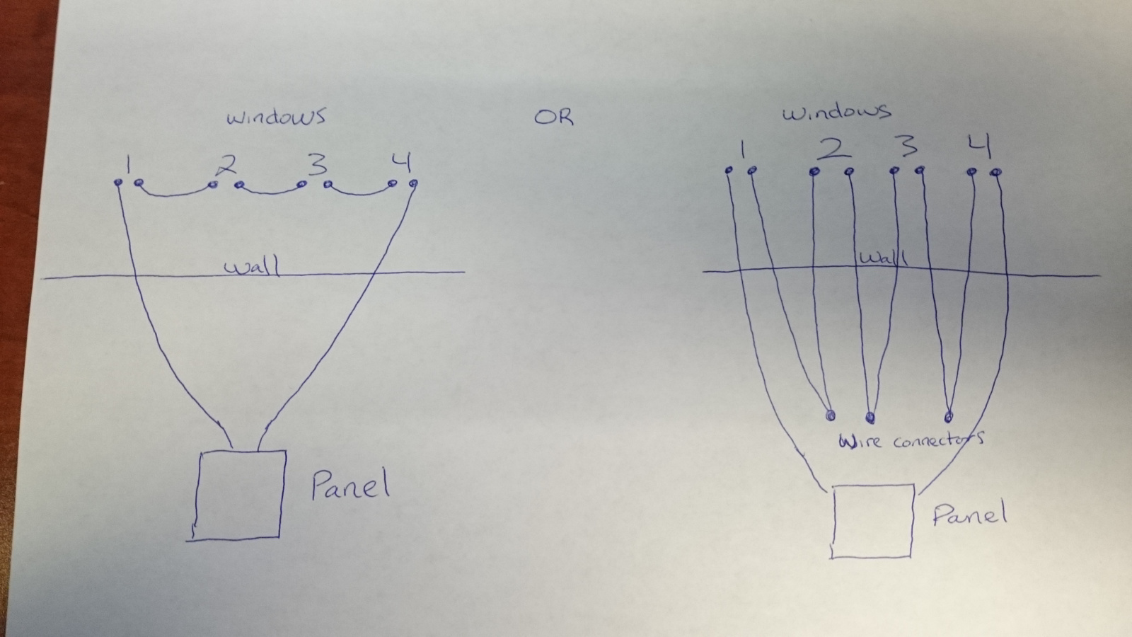
There is a room on the 1st floor with four windows. All windows have hardwired contact sensors installed, but none of them are detected by the panel. No beeping, no sensor activity log, no response under sensor test. Of the “unknown” zones (18, 19, 20), I was thinking maybe this room is the Zone 19 Back Room Laundry (although our laundry is on the 2nd floor), and visually inspected the panel terminal (Zone 3 terminal on the second expansion module), but that’s as far as I got in terms of testing.

Questions:

  • Is there any way for me to utilize the existing HW sensors in the room?
  • If this zone is not reporting any activity to the panel, why is it showing up in the sensor list?
  • If I cannot make the existing wiring work, should I install a couple of wireless door contact sensors? These windows are casement windows, and to be honest, I’m not sure how (or even why) a burglar would try to pry it open from the outside rather than breaking it. I just want to make use of the existing wiring if possible.
    Miscellaneous
  • Panel Time and Date: The panel prompted me to set time and date after the panel was power off for a while last night. This morning, I noticed it had the right time and date showing. Is Time/Date part of the panel-ADC sync process?
  • Should I leave Phone Test to “On”? (I had deleted CS1 phone number as part of activation with suretyDIY.)

Thank you for reading through the long post! Please see all uploaded photos.

– What is the best course of action for me to have a reliable door sensor for Zone 11 (basement door)? Should I get a new plunger sensor? Should I go with a wireless sensor? Any recommendations? – If I install a new plunger sensor and it works, do I need to actively delete Zone 21, as it won’t be used?

If a wired sensor is already there, it doesn’t hurt to try and replace the wired sensor. First you could pull out the current sensor and make sure there is no wire damage or corrosion, and make sure the plunger moves freely and you can routinely open and close the circuit. The plunger may simply be getting stuck, in fact it looks like it is not extending out as I would expect in the image you attached. It may be dirty, or it may be deformed or otherwise damaged.

If zone 21 is not being used you can safely delete it.

– Can you suggest anything I might be able to do to identify what these zones are for? – Should I just delete these three zones? – If I delete the unknown zones from panel memory, do I need to physically disconnect the wires from the panel terminals?

Unfortunately, if the prior installation was not properly labeled there can be some frustrating trial and error. There is really no other way.

This goes hand in hand with the next set of questions, and the big thing here is to determine whether there are any sensors that are unaccounted for anywhere.

A hint for testing, keep in mind that the wired zones at the panel do not need to match the zone numbers in the panel. Physical zone 3 on the Concord terminals could be learned in as Zone 8 in programming if they are deleted and relearned. This is a common confusion on expansion modules.

These zones you mention are all showing as perimeter zones, so they will likely be window, shock, or glass-break sensors. Follow back along the wiring and see if those cables also have pairs connected to aux power. If so there may be Glass-Break detectors hiding. They may have even been removed. Prior modifications that are undocumented can be very difficult.

I would not immediately delete the zones, but if you cannot find them at all and have exhausted searching, yes you could remove them.

Deleting them in the panel would not require the physical wires be removed.

– Is there any way for me to utilize the existing HW sensors in the room? – If this zone is not reporting any activity to the panel, why is it showing up in the sensor list?

Basics of hardwired sensors: the sensor circuit is considered “Closed” when the security sensor(s) are closed. When a sensor opens on the circuit, it opens the circuit and the panel detects infinite resistance. This is how a normally closed circuit will function when wired in series.

The physical sensor doesn’t need to be there for Alarm.com to see the zone. If the panel is programmed to have a wired zone 19 as a perimeter sensor, Alarm.com will show a perimeter sensor as zone 19.

Something silly, but I have seen it in the past, is that the zone may be wired in parallel. This would mean that all 4 sensors on it would need to open to open the circuit. This is an incorrect way of wiring and would have been a mistake by the installer. It is not the most likely scenario, but may as well test as it is easy to do so.

If that is not the case, then you would need to determine which cable in the panel box is associated with those sensors. Is the panel box in the basement? Is the area finished at all? Can you see where the cable comes down from the first floor room where the unresponsive windows are? You may need to physically trace the cable back to the box.

– If I cannot make the existing wiring work, should I install a couple of wireless door contact sensors? These windows are casement windows, and to be honest, I’m not sure how (or even why) a burglar would try to pry it open from the outside rather than breaking it. I just want to make use of the existing wiring if possible.

Wireless sensors are always a good option.

– Panel Time and Date: The panel prompted me to set time and date after the panel was power off for a while last night. This morning, I noticed it had the right time and date showing. Is Time/Date part of the panel-ADC sync process?

Yes, Alarm.com will automatically sync time and date.

– Should I leave Phone Test to “On”? (I had deleted CS1 phone number as part of activation with suretyDIY.)

You should leave auto phone test on.

Thank you, Jason, for your detailed response.

If a wired sensor is already there, it doesn’t hurt to try and replace the wired sensor. First you could pull out the current sensor and make sure there is no wire damage or corrosion, and make sure the plunger moves freely and you can routinely open and close the circuit.

I will check for damage and replace the plunger sensor with a new one and report back. Yes, the existing one looks to be somewhat recessed in the hole even when not depressed. But it doesn’t feel “sticky” and I can press the button in. If it’s a sloppy installation (i.e., unpressed button is too recessed for the closed door to press), shouldn’t the sensor report “door open” all the time? Anyway, I found an unused plunger switch in my garage (GRI PBF-100T), so will try it.

the big thing here is to determine whether there are any sensors that are unaccounted for anywhere.

I’ll do a more exhaustive search, but given that the assigned sensor names are also strange (the rest of the sensor names are self-explanatory whereas these three unaccounted for zone names just don’t make any sense), I’m not hopeful. I wonder if the installer may have hidden a few spare wire runs (that only he knows) in case he was called back to install additional zones? Is that something installers do sometimes?

Or, maybe the installer ran the wires but did not install sensors?

Something silly, but I have seen it in the past, is that the zone may be wired in parallel. This would mean that all 4 sensors on it would need to open to open the circuit.

As for the unresponsive room, I tested by opening all 4 windows at once, and they were still unresponsive. So, assuming that the panel wiring is intact for this zone (based on my very basic visual inspection for any “loose” terminal connections) and assuming that the wires are not damaged between the room and the panel (wire runs are all behind closed walls, so I can’t really do a physical trace), what are the remaining possibilities? Could any of the sensors on the 4 windows be loose or damaged? Is there an easy way to check and repair?

But if the closed door doesn’t depress the plunger enough (because the roller is already too deep in the hole), shouldn’t it report “door open” all the time?

Previously the description of the issue sounded like the sensor would not open. If it is constantly depressed, the sensor may be unable to open reliably. Pressed in = closed.

I wonder if the installer may have hidden a few spare wire runs (that only he knows) in case he was called back to install additional zones? Is that something installers do sometimes?

This is possible, and yes extra wiring is often run at the request of the builder for future use, but you shouldn’t typically see zones in the panel programming for those extra wire runs, there would be no reason to program them as there would be no sensors yet. I wouldn’t expect that to be the case here.

what are the remaining possibilities? Could any of the sensors on the 4 windows be loose or damaged? Is there an easy way to check and repair?

It would be highly unlikely that all of the sensors have malfunctioned in the same way, unable to open. The zone may have been purposefully shorted by a previous installer or occupant for some reason.

You could test by physically removing those sensors, allowing the bare wire to remain open. Does that open the zone? If not that is either not the correct zone or the zone is shorted (closed before the sensors.)

Check the panel terminals, is there possibly a resistor wired in parallel (connected between that zone terminal and a common)

Btw, looks like the spam filter is overzealous regarding the google redirect on the link you posted, we’ve removed that link.

Jason - Thank you. I did further investigation and have an update to share. I opened all 4 windows and looked under the frame. 3 of the 4 had the wired sensor installed; 1 did not. Please see attached photos for window locations around this corner room. Window 3 is missing the sensor. Previously, I saw the magnet contacts on the window itself and assumed all sensors had been installed. I should have caught this at the time of installation 3 years ago. Live and learn, I guess.

After this discovery, I remembered seeing a loose wire in the panel, went back to the panel to check, and saw what could be the wire from this unresponsive physical zone. (So, after all, this zone may never have been terminated in the panel, although I’m not 100% sure.)

Given the findings above, do you have further guidance/suggestions?

Is there a way to still make use of the 3 windows that have sensors installed? I only see one wire in Window 3 entering the hole to the bottom and also saw a short wire fragment 7" in length kind of stuck in the frame. To clarify, the 7" fragment is really just a fragment, with both ends cut and not connected to anything. It was just there wedged in the wood frame.

Does Window 3 make the entire zone unusable? Is there a way to test?

On the panel side, I found an unterminated wire coming out of the wall that looks like the same wire type (brown, 2 stranded conductors). Could this be the wire that runs to the room? Looking at the other wires in the panel, it looks like I’ll need a resistor and a wire nut (or b-connector)?

On a side note, this is almost becoming an addiction! I’m so mad at the installer (and at myself for not checking) that I want to go further before admitting defeat. :wink: I accept the likelihood that zones 18, 19 and 20 will remain a mystery forever, but at least I’m learning a few things…

Windows.png

Windows-1-and-2.jpg

Windows-3-and-4.jpg

Just want to add a photo of the loose fragment from window 3 if it means anything.

Wire-fragment.jpg

Previously, I saw the magnet contacts on the window itself and assumed all sensors had been installed. I should have caught this at the time of installation 3 years ago. Live and learn, I guess.

After this discovery, I remembered seeing a loose wire in the panel, went back to the panel to check, and saw what could be the wire from this unresponsive physical zone. (So, after all, this zone may never have been terminated in the panel, although I’m not 100% sure.)

Given the findings above, do you have further guidance/suggestions?

On the panel side, I found an unterminated wire coming out of the wall that looks like the same wire type (brown, 2 stranded conductors). Could this be the wire that runs to the room? Looking at the other wires in the panel, it looks like I’ll need a resistor and a wire nut (or b-connector)?

Well that is frustrating! The way you would want to test this then is with a multimeter so that you can measure resistance on the circuit. I’ll go over the steps below, but it would require access to all window wires, and it sounds like one window may be unable to complete the circuit.

Remove the wires from all of the window sensors in that room and twist the wires together to close the circuit. Measure the resistance between the two wires at the panel you believe to be the other end of that circuit. Is the resistance 0 or close to 0?

Next Open the circuit by untwisting the wires at one of the window locations. Measure resistance again at the panel end. Is the resistance infinite? (your multimeter may use different methods to indicate a fully open circuit, check the manual to determine)

If you can open and close the circuit by connecting and pulling apart the wires at the windows, yes that would be the other end of the circuit. If the resistance reading does not change, no, it would be different wires.

Is there a way to still make use of the 3 windows that have sensors installed? I only see one wire in Window 3 entering the hole to the bottom and also saw a short wire fragment 7″ in length kind of stuck in the frame. To clarify, the 7″ fragment is really just a fragment, with both ends cut and not connected to anything. It was just there wedged in the wood frame.

Does Window 3 make the entire zone unusable? Is there a way to test?

If you cannot pull the wire up and find another conductor, yes, unfortunately if wired in series that zone would always be open due to that one window.

It would usually be much easier to replace with wireless sensors.

On a side note, this is almost becoming an addiction! I’m so mad at the installer (and at myself for not checking) that I want to go further before admitting defeat

The puzzle-like problem solving aspect can definitely be fun, even if the reason you need to do it is infuriating. We love the DIY spirit! The more you learn about the system the easier it becomes to maintain and upgrade.

Remove the wires from all of the window sensors in that room and twist the wires together to close the circuit. Measure the resistance between the two wires at the panel you believe to be the other end of that circuit. Is the resistance 0 or close to 0?

Even if I twist the wires together on the three windows with sensors, if the one window (#3) with no sensor is open, then the resistance will still be infinite, no? Or, are we assuming that window 3 was simply bypassed and can be considered part of a closed circuit (there’s no switch)?

If you can open and close the circuit by connecting and pulling apart the wires at the windows, yes that would be the other end of the circuit. If the resistance reading does not change, no, it would be different wires.

Understood - I just feel tempted to test the resistance with the wires intact in the sensors first (I woulud need a right angle screwdriver to access, etc.). If the sensor-magnet pairs are working properly, then the open and close test should work, no?

If you cannot pull the wire up and find another conductor, yes, unfortunately if wired in series that zone would always be open due to that one window.

Would it be possible to cut the wire and simply insert a sensor in the cut to re-complete the circuit? Sorry, this question may be a result of me not completely understanding how a series circuit is made. I was guessing (hoping?) a new sensor can be inserted in the middle of the circuit. Please see attache photo.

Lastly (don’t want to get my hopes up, but), if I found the right wire and if the sensors are working, what do I need on the panel side to complete the installation? Just a resistor and a wire splice connector, right?

Thank you thank you!

Insert-missing-sensor.jpg

From above: “I’ll go over the steps below, but it would require access to all window wires, and it sounds like one window may be unable to complete the circuit.”

From your description before it sounded like window three has only one wire available. Is that correct? There should be two conductors there. If there is only one, with a cut end, no that circuit would be open if it was wired in series with the rest.

Do you not see a cut end to the wire on window 3? Are you saying you think it connects directly to the next window? You could verify this with a multimeter if you knew which wires in the panel were to that circuit.

If it is just one cut wire, it is entirely possible that they did not run a conductor from that window to the next by accident, and it was not able to be used, or that the wire broke and was irretrievable in the wall. Any number of things may have caused this, but the end result would likely be an open circuit if the wires were pre-run in the home.

Now, did the installer you hired run all the wires during the installation? If so they would probably be wired in series at the panel, not in the wall. See the attached diagram. It will take a multimeter and some trial and error, but in this case you could simply remove the third window from the equation.

It all depends on how much troubleshooting is worth the cost of 4 wireless sensors.

If the sensor-magnet pairs are working properly, then the open and close test should work, no?

Yes, I suggested removing the wires and connecting the wire to know for certain that the circuit is physically closed. We want to isolate any possible problems, but you would probably be safe just leaving the sensors on if you wish.

Would it be possible to cut the wire and simply insert a sensor in the cut to re-complete the circuit? Sorry, this question may be a result of me not completely understanding how a series circuit is made. I was guessing (hoping?) a new sensor can be inserted in the middle of the circuit. Please see attache photo.

Lastly (don’t want to get my hopes up, but), if I found the right wire and if the sensors are working, what do I need on the panel side to complete the installation? Just a resistor and a wire splice connector, right?

If the wire is simply bypassing window three, and it is an uncut conductor going from window 2 to 4, yes, you could cut in the middle and insert a sensor if there is enough slack.

Yes you would need a resistor (there are usually extras left in the panel housing) and a wire connector.

Thank you for the hand-drawn diagram! I was wondering about that (series in the panel or in the wall). To be honest, I was afraid to mess with the clump of wires in the panel, as it’s very crowded in there with poor labeling. As of now I’m not sure if he did the series wiring in the panel or before. I’ll find out.

Do you not see a cut end to the wire on window 3? Are you saying you think it connects directly to the next window? You could verify this with a multimeter if you knew which wires in the panel were to that circuit.

Attached photo of window 3 shows one conductor coming into the frame and entering the hole to the bottom. So, I do not see a cut end to this wire. Separately (for more confusion), I found a short wire fragment with both ends cut in window 3. As you said, any number of things could have happened and I need to verify if the partially visible wire going into the hole in window 3 is simply passing through window 3 to the next window.

If the wire is simply bypassing window three, and it is an uncut conductor going from window 2 to 4, yes, you could cut in the middle and insert a sensor if there is enough slack.

There’s definitely not enough slack. If I can verify a closed circuit (without window 3), I think one option is to add a wireless sensor to window 3 and put it in the same zone as the three other wired sensors; that’s possible, right? I’ll pull on the wire in window 3 to see if there’s slack hidden in the wall, although it felt pinched in the wood frame when I checked yesterday.

Thanks again.

If the wire in window 3 has a cut end in the wall (which seems more likely than an accidental or intentional direct connection between 2 and 4), my options are down to:

  1. if series wiring is in the panel, then remove window 3 from the series and add wireless to window 3; or
  2. give up on this wired zone and go wireless on all 4.
I think one option is to add a wireless sensor to window 3 and put it in the same zone as the three other wired sensors; that’s possible, right?

No, wireless sensors all use their own individual zones.

The wired sensors are grouped together only because they are physically wired that way.

If the wire in window 3 has a cut end in the wall (which seems more likely than an accidental or intentional direct connection between 2 and 4), my options are down to: 1) if series wiring is in the panel, then remove window 3 from the series and add wireless to window 3; or 2) give up on this wired zone and go wireless on all 4.

Correct. If you enjoy the problem solving, it’s definitely worth it to give the troubleshooting a shot. When working on wired sensors you’ll definitely want a method of measuring resistance.

Here’s how I came out on the troubleshooting.

Basement door: I replaced the wired plunger sensor (malfunctioning) with a new one, and it works consistently now. The old one had the button depressed much of the way and was performing erratically.

Unresponsive zone: I took resistance measurements, and as you suspected the physical circuit doesn’t seem to be closed (window 3 only has a single conductor). I’m moving on to wireless sensors, but that was educational, thanks to you.

Now, I had some questions about wireless sensors to go with Concord 4 in general.

Qolsys and GE: Are Qolsys 319.5MHZ sensors compatible with Concord 4? There seem to be comparable models under both Interlogix and Qolsys brands. Are they basically interchangeable? (door, motion, glass) Is learn-in done any differently?

In a recent post, you stated:

Second, and more importantly, an Image Sensor cannot simply replace any spot where you might want to install a 319 mhz or wired motion detector.

This is less of an issue with all-in-one panels since the module/transceiver is located in the main control touchscreen, typically on the first floor fairly centralized, and Image Sensor placement can be a bit more haphazard.

With a Concord, the Image Sensor receiver is in a daughterboard connected to the cell module. The cell module, while capable of being wired in a centralized location on a ground floor, is typically just mounted in the basement near the alarm panel can, resulting in a further distance and more materials through which an Image Sensor signal needs to travel. So signaling is affected by module placement and where you intend to install the Image Sensors.

Just to confirm, does the ADC cellular communicator (for Concord) come with the above mentioned daughterboard built in, or is it something that needs to be purchased separately?

Is the Qolsys image motion detector compatible with Concord 4’s ADC module?

Lastly, for image motion detection, 40 images come with the ADC Gold plan. Does that mean the image detector stops sensing motion after 40 images are captured for any given month, or does it keep working but without recording the image?

Qolsys and GE: Are Qolsys 319.5MHZ sensors compatible with Concord 4? There seem to be comparable models under both Interlogix and Qolsys brands. Are they basically interchangeable? (door, motion, glass) Is learn-in done any differently?

Not all would be. I would recommend sticking to Interlogix as their sensor line is more robust than early Qolsys sensors. The newer S-Line sensors would not be compatible.

Just to confirm, does the ADC cellular communicator (for Concord) come with the above mentioned daughterboard built in, or is it something that needs to be purchased separately?

No, the cell module does not come with the daughterboard, but the Image Sensor can be purchased by itself or in a kit with the daughterboard. See this post for details.

Is the Qolsys image motion detector compatible with Concord 4’s ADC module?

Technically yes, only the 2GIG Image Sensors are different models, but the Qolsys branded one would not come with the necessary daughterboard.

Lastly, for image motion detection, 40 images come with the ADC Gold plan. Does that mean the image detector stops sensing motion after 40 images are captured for any given month, or does it keep working but without recording the image?

The image sensor’s local function as a motion detector is never interrupted. The 40 limit just refers to uploads. Note that while alarm-triggered images count toward the total, they are always uploaded even past the total (similar to cloud video limits).

Wow…
Tough Install to troubleshoot from your picks.

Some info tools that may help…

If you have access to Installer programming, in SENSORS field you can use EDIT SENSORS to see current installed zones. Partition and groups are labeled there.

In SENSOR TEXT programming fields it us just that…text. in fact a deleted zone will retain the original text. Not true on the Alarm.com app.

So, using this information…in EDIT SENSOR field… record each sensor not on P1 [partition 1]…probably all are P1…but if not…then we can find out more about what may have been done to combobulate your system.

As you go thru this EDIT SENSOR field one sensor at a time, record the group for each sensor in the list that is currently programmed.
Groups like 10/13 are commonly associated with Doors & Windows.
Group 15/17 Motion sensors and
Group 26 are Fire sensors. Group 0 or 1 are associated with panic buttons and are commonly used with keychain remote fobs.

Also you have a 6/2 snap card attached to the Mother board.
6 standard zones with their own zcom (must be used properly) and 2 fire/2wire smoke.
Two wire and four wire smokes are a different animal. Most Concord installing companies when using THESE two zones for fire will use a 2 wire smoke.
On the Motherboard…zone 8 is also capable of using as a 2 wire smoke zone.

2 wire smokes delivers +/- power over initiating circuit and provides supervision where a four wire model requires an additional part to supervise the +&- wires.

Not required for the 2 zones on snap card that are designated ONLY for 2 wire smokes…but Zone 8 on Motherboard…if used with and for 2 wire smoke(s)…needs a line in programming [accessory modules -inputs] to be activated [two wire smoke off ->ON!].

How to tell? Use edit sensor fields for Zones (group 26) and see if you have 3 zones labeled with Group 26.
Top floor (18?)
Main Level (19?)
Basement (20?)

*also worth noting in EDIT SENSORS is each ‘programmed’ zone tells us if it was learned in as HW or RF.

Another issue I see alot of times is text is never really updated in panel when a skipped zone is reused and learned in elsewhere in the system. So text descriptors are not always true.

Those window sensors? Well if you can not repair the wiring, and the guys above really did you well explaining a series circuit, then wireless is a good option. I would not use the same zone number originally programmed for that 4 windows. With Wireless you will probably just use 4 sensors. If you can buy from Ebay or Amazon some of the crystal sensors…in contrast to SAW sensors…you will get 4x range capability and 5-7 years MORE battery life than the new sensors.
Some micro sensors are crystal and are about less than $20 each! I would definately put in a new 2032 coin battery and I like the ultimate Lithium style from the bunny hopper that goes and goes. Try putting your new wireless zones up on zones 30ish in number. Then delete old zone and change the deleted zone descriptor. I JUST ADD “DELETED” AT END OF TEXT.

Lastly, a wireless zone (RF in Edit Sensors field) does not show up as a problem unless it us a)open b)low battery or c)supervisory. Thus if is removed from the property it WILL BE in a supervisory state.

In case you solved your issue, ill will truncate now but feel free to ask anytime. I have concord 1.6 purple heart badges! (Some of you guys will get it). I go all the way back to ITI days of the SX-IVB [1985] and have 39 years in residential security. I have rescued worse wired panels than your pics.

I know what you are up against. It takes a smart technician to do what you are attemoting to do and this forum can point you in the desired direction but your feedback is soooo important.

The fact YOU took the time and explanation of your problem is why I registered here to respond to you.
No matter what anyone tells you…the Concord 4 platform was and still is one of the mist reliabke functioning residential systems in my times doing Alarm sysytems. I take pride in helping my fellow installers when they run into these type systems.

Lastly, and it could be the angle of the picture taken…but it seems to me the 6/2 snap card may be wired incorrectly for the 2 wire smoke circuits.

ALARMtech.