Does the Aeon Labs DSC26103-ZWUS need to have a switch wired in to it? I want control 3 lights out of say 5 via the Aeon controller, but want all 5 to turn on when I flip the actual light switch. Is that possible?
If I draw out my idea on paper, it makes sense, but I’m worried that when I actually flip the switch, it will blow up the module (somehow).
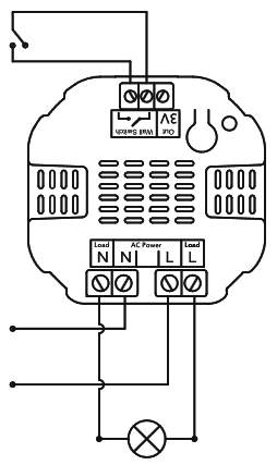
I don’t think the micro switch would need to physical switch wired to it. It depends on which mode you program it in. You could program it in 2-state (flip/flop) mode and just connected the switch terminals with a wire and that would be like the switch is always on. Or you could put it in momentary mode and just leave it disconnected.
So the question is will the Micro Switch be damaged if you apply 120V to the L (Load) terminal which is intended to output 120V, not receive 120V, right? I don’t know. You should probably ask Aeon Labs about that.
Assuming it is safe for the Micro Switch, I’m wondering if the logic would work. It’s a circuit with 2 switches - W (wall switch) and Z (z-wave switch). It sounds like what you want is
W (off), Z (off) = 0 lights on
W (off), Z (on) = 3 lights on
W (on), Z (off) = 5 lights on
W (on), Z (on) = 5 lights on
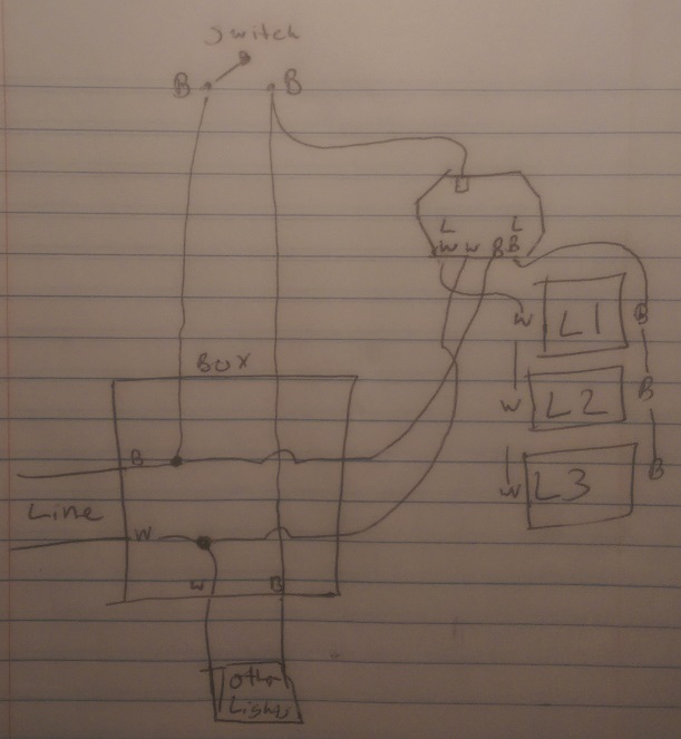
Is that right? If so, I think in the case of W (off), Z (on) that would turn all 5 lights on because of the connection in the upper right of the box. Wouldn’t it?
Ryan - Yes, you got the question right and looking at the drawing again, yes, W (off) and Z(on) would cause all 5 lights to turn on so this idea won’t work. At least the way I have it drawn out now won’t work.
I think I could get it to work if I knew I could pass 110v to the switch side of the module. If that’s possible. I can make this work. I guess I’ll have to contact Aeon about that.
So, it looks like you can pass a hot wire feed to the switch side of the unit. So 2 attachments are below:
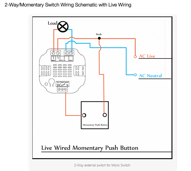
1 - The basic wiring to follow for pushing 120v to the switch side of the switch side of the module. The diagram says momentary, but reading the full document, you can use a standard 2 way switch. Full info here: http://aeotec.com/support/1219-micro-switch-wiring-schematics.html
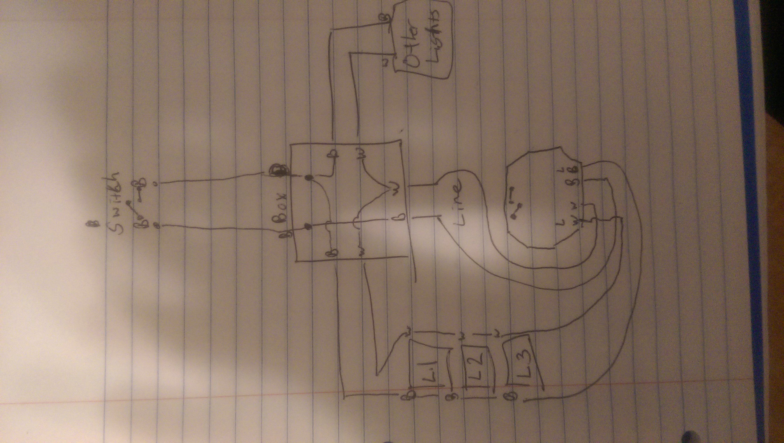
2 - My crappy drawing of how I’ll be utilizing the module.