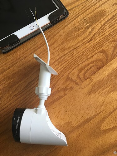
Hurricane Ian blew our camera off it’s soffit mounting and left the power source wires dangling… We want to reconnect the camera wires to the power source wires. Camera has 3 wires. Black, white & yellow. Power source has 4 wires. Black, white, red & green. Which wires should we reconnect to the camera to get it connected again? TY
The camera has a white tail with barrel and terminal connectors. Based on the description, are you saying that the tail was torn off the camera?
So we can best assist, can you post a photo of the wires you are referencing?
Hi Jason. Here is pic of v722w camera detached by Hurricane. 3 wires, B, W & Y. Was attached using barrel connects. The power source is 12 volt and has 4 wires. B, W, R & G. I assume I would reconnect black-to- black, white-to-white. But does the camera’s yellow wire also need to be connected?
There is no standard troubleshooting for this circumstance unfortunately as the tail should never be cut.
I don’t have that model in front of me at the moment, but there is no data wire in the 722W tail, so it is possible that the white and yellow are both positive for the terminal and barrel connector respectively. The camera documentation does not diagram the internal wiring. White and black would likely be + and -
I cannot provide guidance on the power supply given the description, the plug in power supply cable should have two conductors, not four. Are you using a separate cable to lengthen it or using a different power supply? The correct wires would be based on which are spliced to + and which are spliced to -
Hi Jason. Yes, apparently whomever installed camera used a 4-wire cable to lengthen. Two of the 4 wires give a 12 volt reading while other 2 give zero volts when tested. So based on your email sounds like I connect camera W & Y to a 12 volt wire and camera B to one of the zero volt wires to complete the circuit. Sound right?
Two of the 4 wires give a 12 volt reading while other 2 give zero volts when tested. So based on your email sounds like I connect camera W & Y to a 12 volt wire and camera B to one of the zero volt wires to complete the circuit. Sound right?
How are you testing the conductors? Are you testing with a multimeter/voltmeter? To clarify, the meter would only detect and accurately show the voltage when you have a circuit completed by the probe wires.
This means you would see 12V DC when a positive wire is on your Red/Positive probe and when a negative wire/GND is connected to the Black/Negative probe.
Is this how you determined which wires are positive and negative?
If there is any question about which conductors are + and -, I would recommend checking at the power supply cable where it is spliced which conductors are connected to which side just to be sure.
Both positive should be spliced to the positive on the camera (likely white) and both negative should be spliced to the negative on the camera (likely black)
I am assuming that yellow is the other positive input because there are two different power input options in the tail when it is intact. You would not need to use both inputs though.
Thank you Jason. For your patience and assistance. I only needed to connect 2 wires to the camera as you explained. The pos to the white, the neg to the black. You rock.
Anthony
Regards,
Anthony J. Maro
