I have hooked up the takeover module to my current alarm panel as instructed but the 2gig control panel is not recognizing the sensors. Am I missing something? The module was suppose to come pre-programmed.
Verify install and programming: 2GIG-TAKE
I have done this
Have you actually programmed the sensor zones?
Program your takeover module zones.- Choose a Sensor Type appropriate to the zone. (Interior Follower for motion detectors, Entry Exit for entry doors, etc.)
– Equipment Type will be 2GIG Takeover Module.
– Sensor serial ID will be the following:
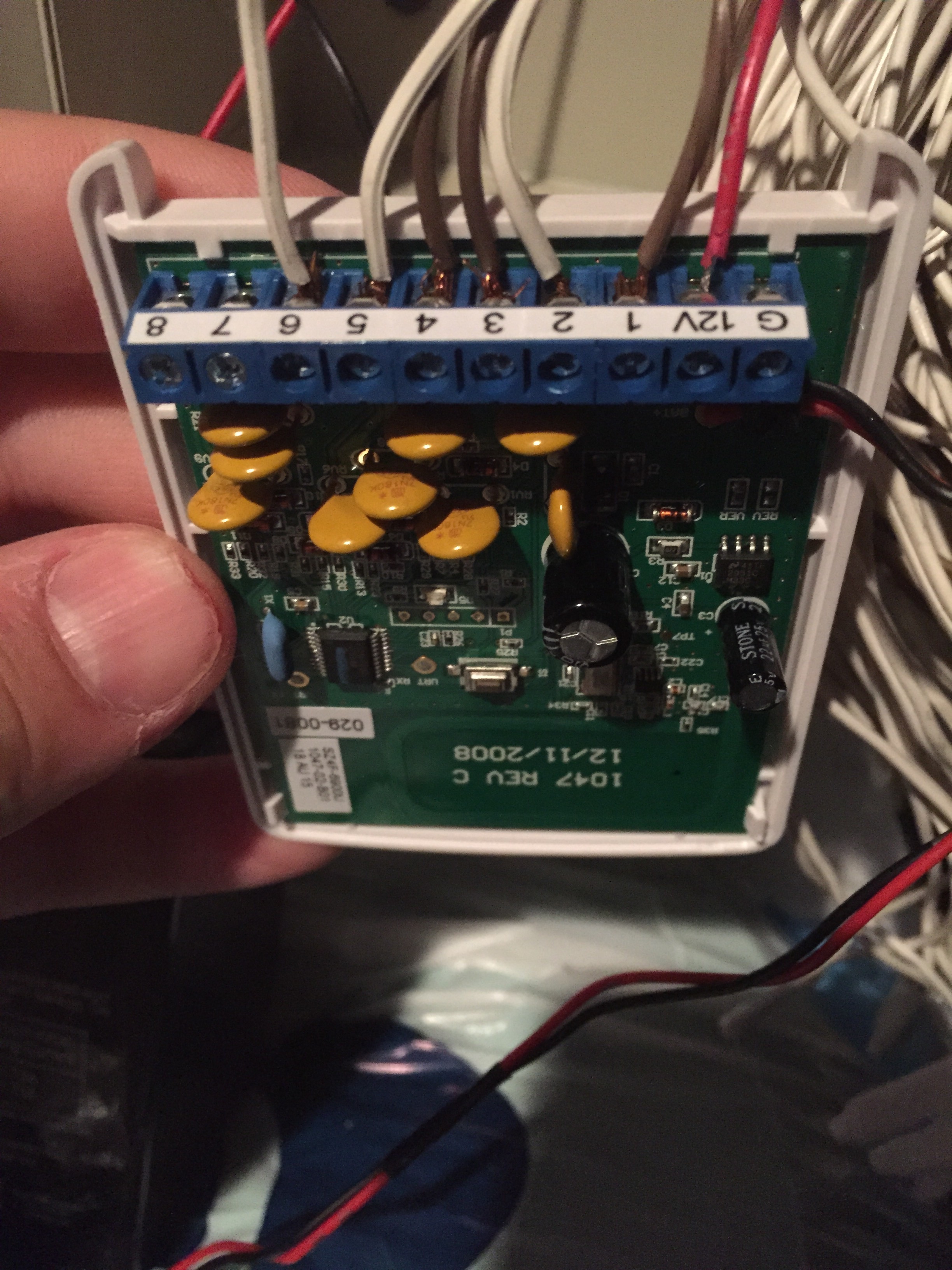
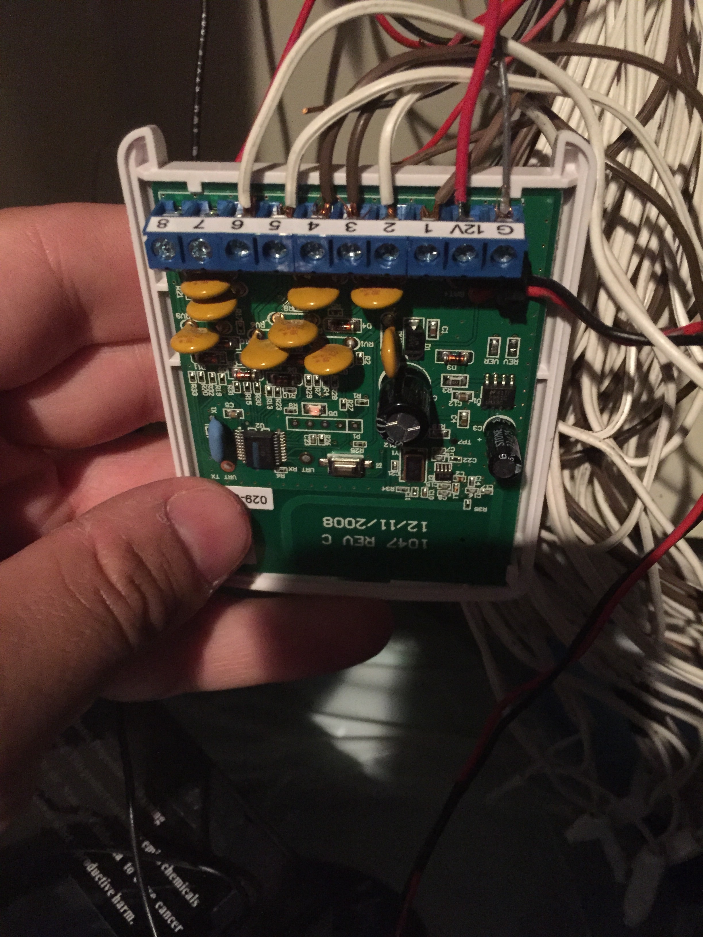
Zone 1: Seven digit TX ID on Takeover Module label (always ends in 1).
Zone 2: Same first 6 digits, end with “2”
Zone 3: Same first 6 digits, end with “3”
Zone 4: Same first 6 digits, end with “4”
Zone 5: Same first 6 digits, end with “5”
Zone 6: Same first 6 digits, end with “6”
Zone 7: Same first 6 digits, end with “7”
Zone 8: Same first 6 digits, end with “8″
– Loop will always be 1 for takeover module zones.
– Select a voice descriptor.
– Enable reports and supervision.
– Choose whether or not that zone should chime.
Your panel will reboot once you exit programming, saving changes. When it powers back up, test your system.
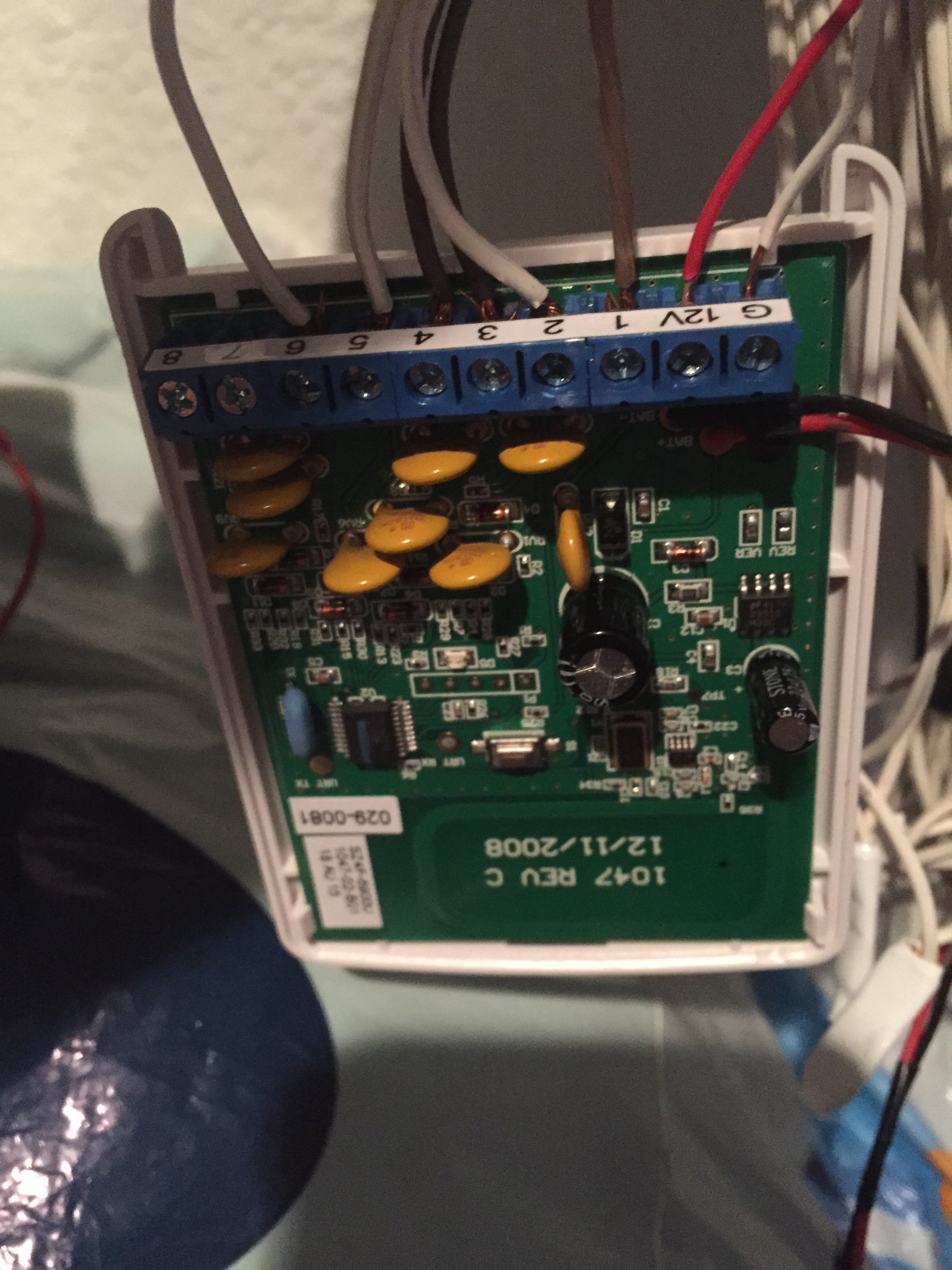
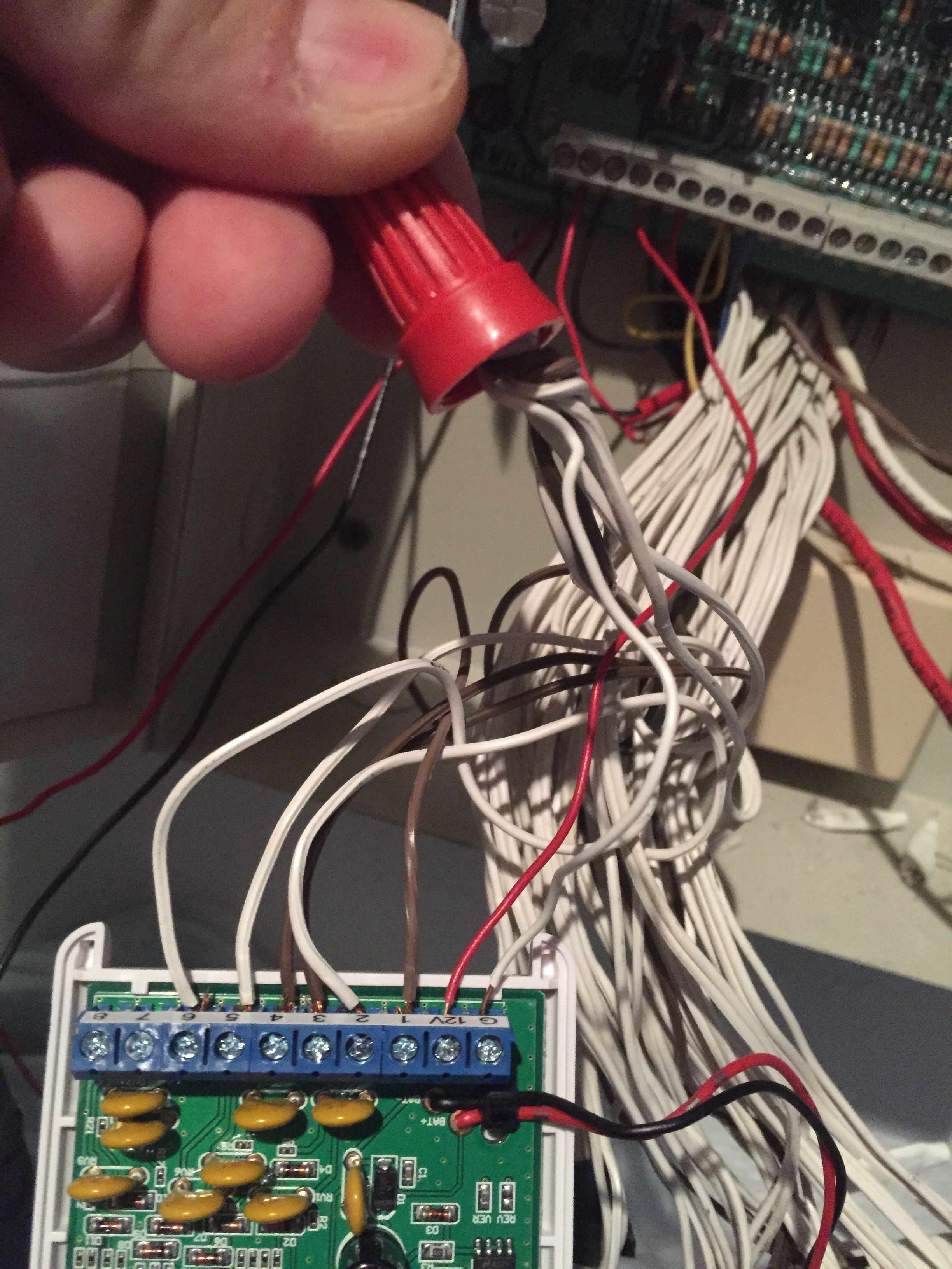
It looks like you have no ground wire connected. The takeover module is not powered.
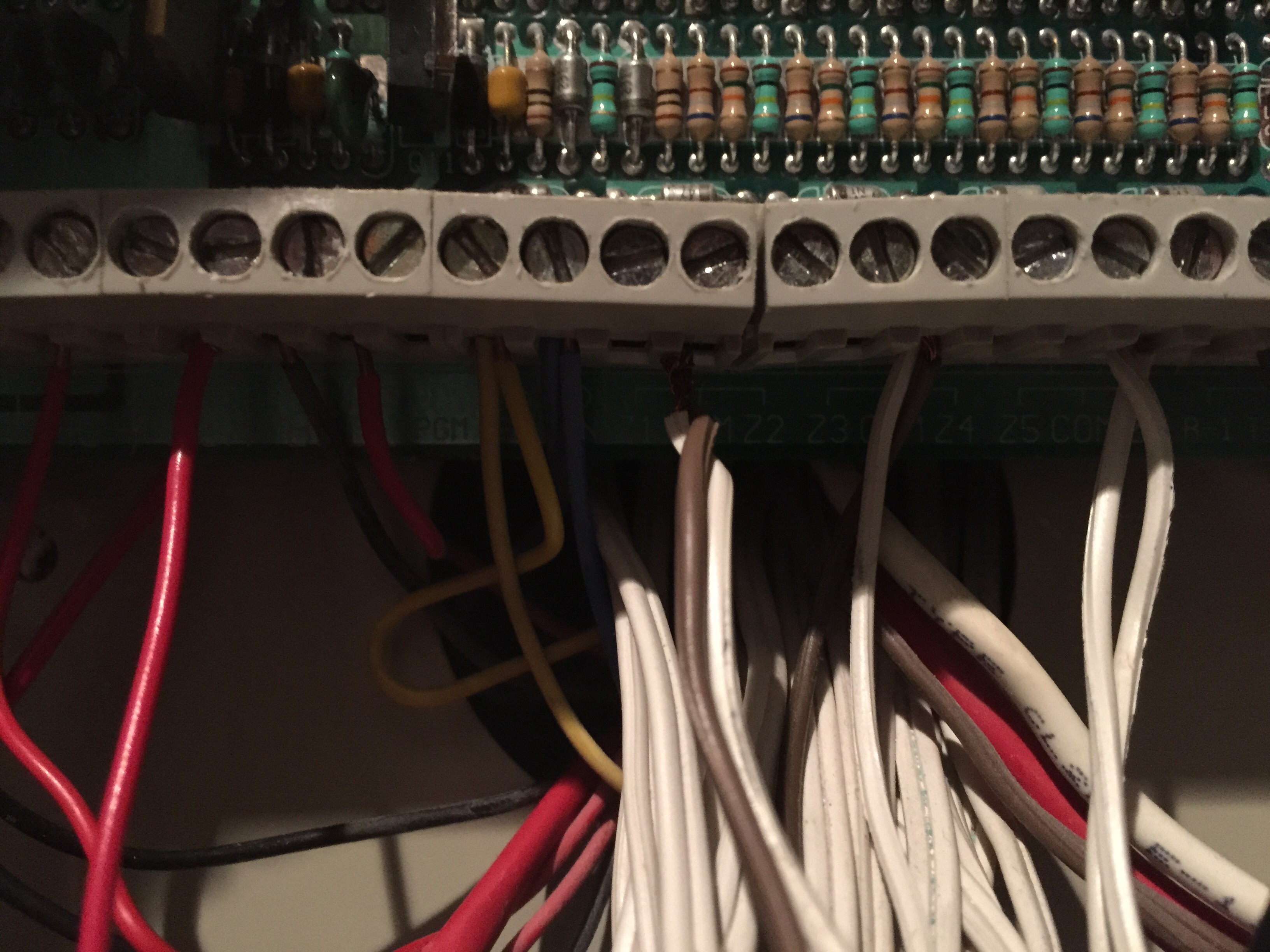
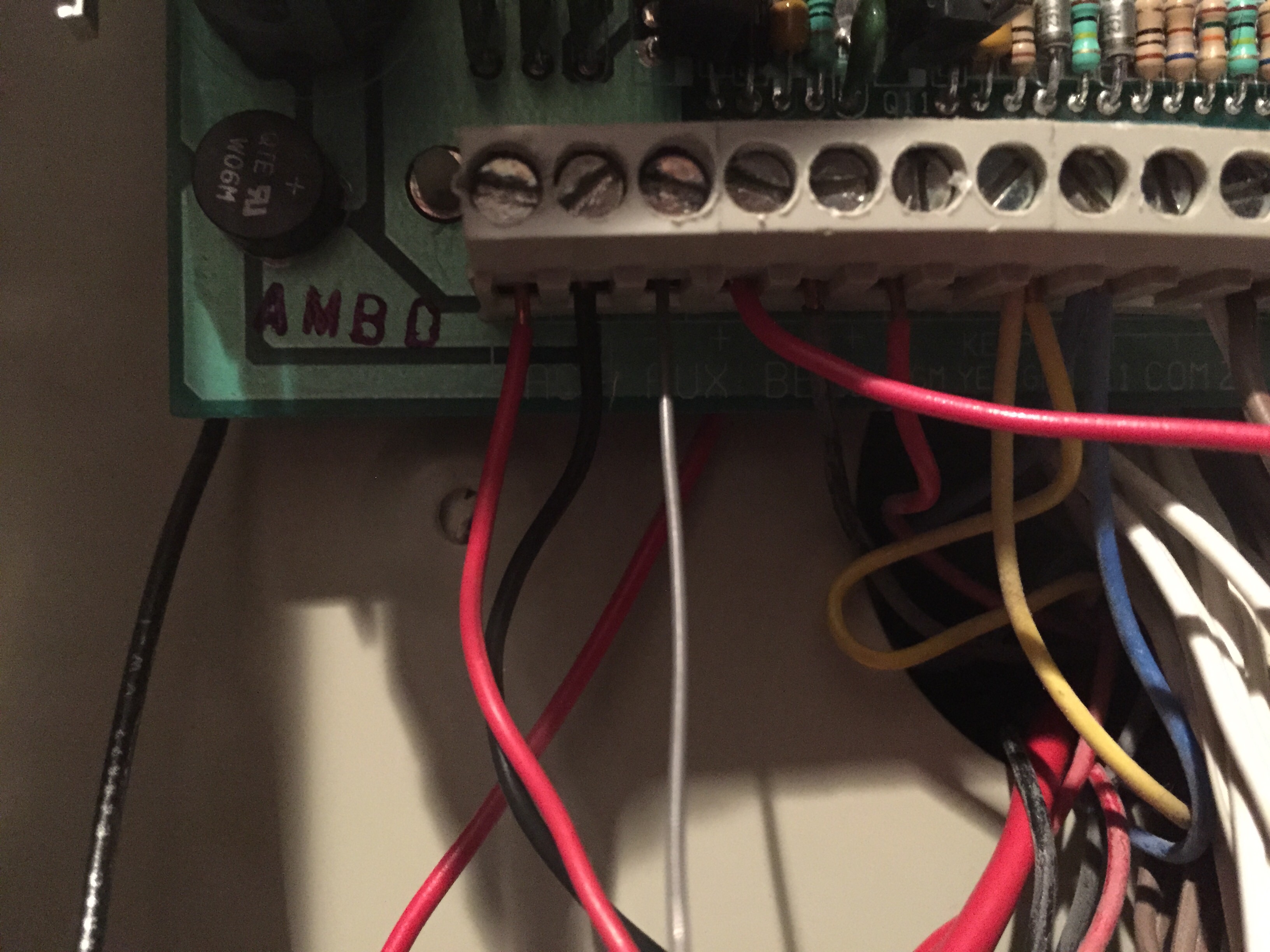
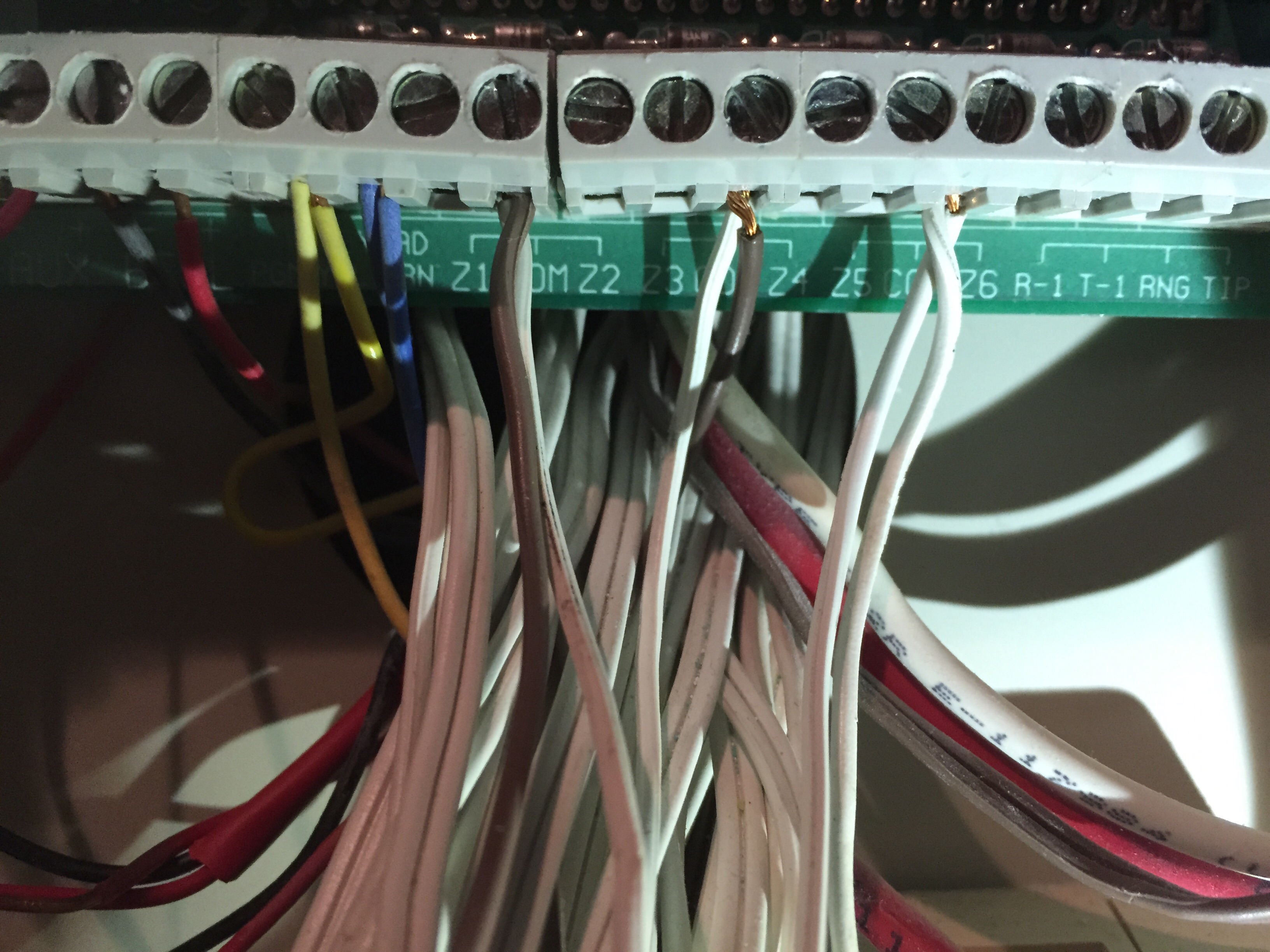
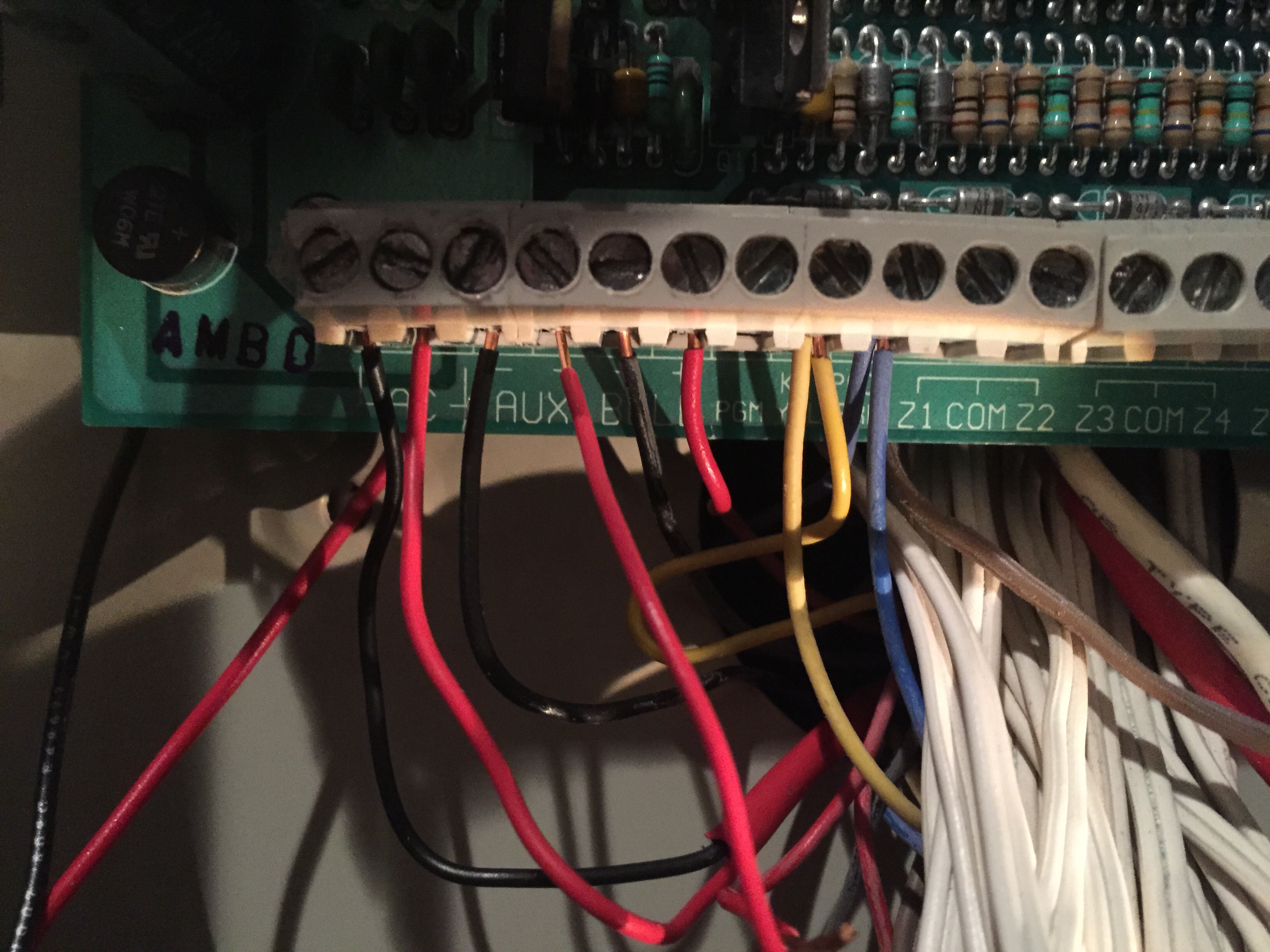
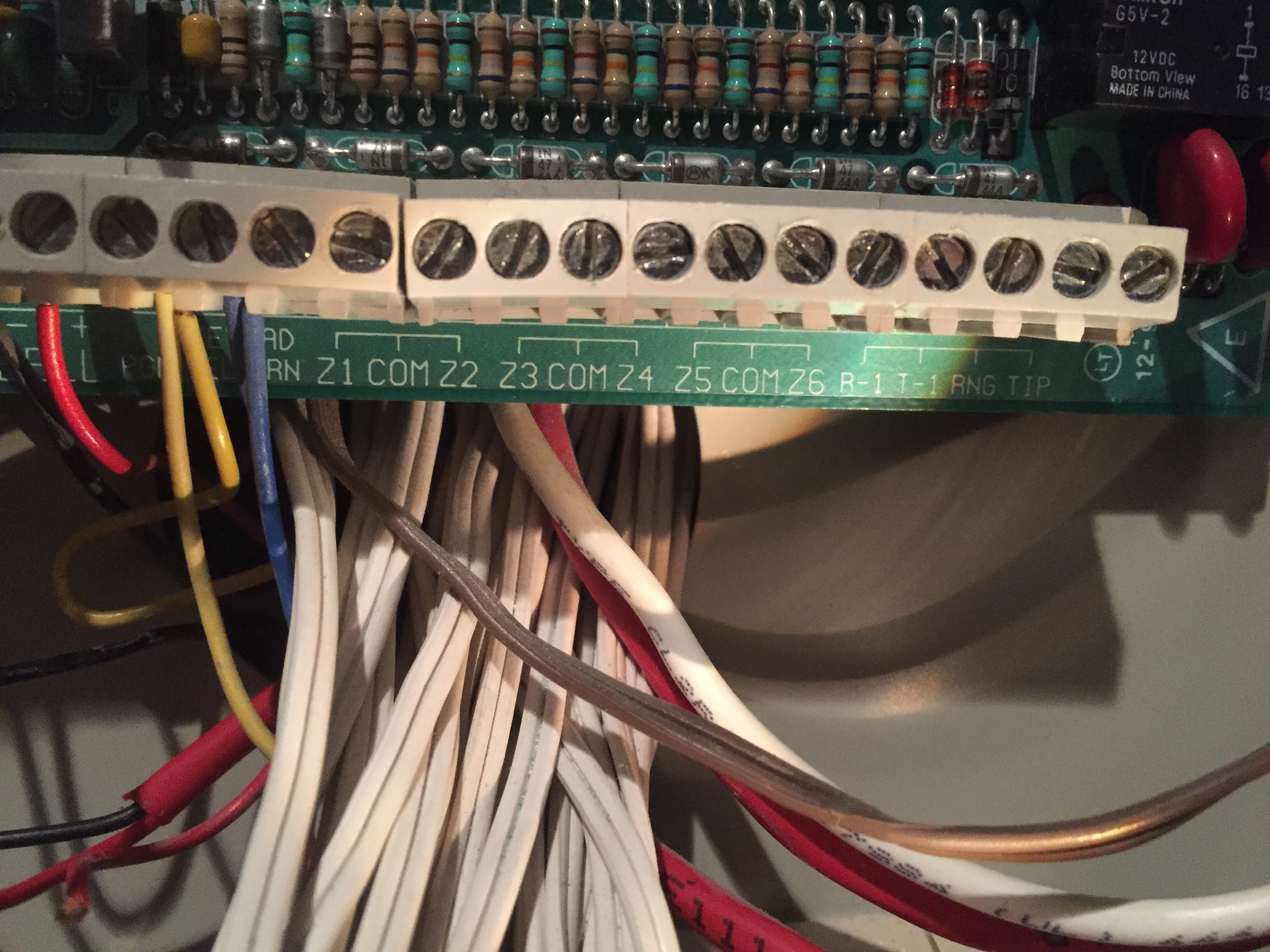
Yes, it was pre-programmed. The G terminal on the super switch should be connected to the ground terminal on your existing panel and one of the sensor common terminals on your existing panel. Can you take a better pic of your existing panel? One that shows all the screw-down terminal connections and the labels on all those terminals? The labels are things like +12, Z1, Z2, C, etc…
This was during my troubleshooting but I do have a ground and power wire going to the auxiliary + and - of the existing panel. The takeover module has a red light on so I am assuming it is getting power. I have left the common wires plugged into the existing panel as well. I have confirmed programming on the 2 gig module. The control panel is still not recognizing the sensors. Any other ideas? Thanks
You can try using a wire nut or the like to splice all of the zone commons together, with a jumper spliced in and also connected to the G terminal on the Takeover. This is the other installation method. Do you know if the existing panel was working properly or not?
I assume it has been done during troubleshooting but if the panel is powered before the Takeover module I have seen them not communicate properly at first. Can you power cycle the panel?
Another option is to leave the all the common wires where they are and add a jumper between any one of the commons and the AUX- terminal. The commons should all already be connected to each other inside the panel but AUX- is often not connected to them so you would have to use a wire to make that connection.
Good job on using AUX+ and AUX- instead of the AC terminals. Many people make the mistake of trying to power the super switch with the AC terminals.
Another thing you can do is verify the super switch zones by individually by unhooking the sensor wire from the one of them and instead using a jumper wire to temporarily connect that sensor input to the G terminal. The control panel should show the zone opening and closing when you do that.
Do you have a multimeter?
I have tried to connecting all
Of the common wires to the ground by using a jumper and sensors are still not being recognized. I was able to pickup a multimeter. How would this help troubleshoot the problem?
It is pretty rare, but check the resistance of your sensor circuits. The Take-345 lists a maximum allowable resistance of 3k ohms. If you have end of line resistors that are 10% above that or more, your TAKE may never register any change on the circuit.
The red LED light on the takeover is no longer lit. Does that mean the module is not getting power? I have been trying to get this to work for two weeks and I dont understand why it wont work. I am not an electrician but I do have a basic understanding of wiring. I reference to your last post, I am not sure how to test the end of line resistors. Unfortunately, it looks like I am going to have to give up on the wired sensors and switch to wireless. any last words of advice?
My current set-up. Additionally I noticed that when I disconnected the existing alarm panel downstairs, the power to the upstairs keypad went off. I’m not sure if this has anything to do with power to the existing control panel.
Well, it could always indicate a bad/damaged TAKE-345. Since you have the multimeter, can you remove the wires connecting to your old control panel Aux + and - and test the DC voltage between those two terminals? Is it producing roughly 12 VDC?
Ok so it’s looks like I am getting no volts from the auxiliary terminals. I was originally getting power but that must have been from the backup battery. I don’t see an ac source of power plugged in near the control panel. Is this usually in a different place ie the attic? I’m not sure why the power would have stopped as the previous keypads were functioning before I took them off
Looks like I am getting no power to auxiliary. I had power before but I bet that was from backup battery. I can’t find where the alarm panel is receiving its ac power from. If I run a new ac power to the existing panel would my hardwire sensors still get power? I guess I’m asking do the hardwired sensors get power from the existing panel or are they wired to power elsewhere?
I was able to pickup a multimeter. How would this help troubleshoot the problem?
Electronic signals are invisible. The multimeter gives you eyes. It helps you divide and conquer to isolate the problem.
Wired sensors are based on resistance. The multimeter helps you verify that they’re working. You’ll measure one resistance value (infinity Ω or overload) when they’re open and another resistance value (0 Ω or the EOL resistor value) when they’re closed.
If you’re not getting 12VDC out of the AUX terminals then that would definitely be a problem. Are you measuring 16.5VAC on the old panel’s AC power input terminals?
I guess I’m asking do the hardwired sensors get power from the existing panel or are they wired to power elsewhere?
Wired sensors such as door/window contacts don’t get power. If you have wired motion detectors or glass break detectors then they would get 12VDC from the AUX terminals. Wired sensors such as these which need power will have 4 wires going to them, two wires for 12VDC power and 2 wires for the alarm signal. The 2 alarm signal wires are not powered and they behave exactly like regular door/window contact wires.
Well you can check the AC input terminals directly. Typically, alarm panels use a 16.5 volt transformer. Test for AC voltage and look for roughly 16-17 volts between the AC input terminals. That will tell you if it is powered.