Need some help to install my wireless takeover module and have it linked to the GC3 panel. I have completed the wiring for the 2gig wireless takeover kit; Zones 1-4 are window/door recessed contacts and Zone 5 is the motion detector. After trying to set up the wireless zones on the GC3, it only detects the motion detector (zone 5). I have also tried the learn function for each of the other zones and it’ll default back to the motion detector after a while.
The high wires from an existing DSC panel are going into the module and the low are twisted together with the ground. I have tried both new/existing equipment settings and confirmed that the numbers are sequential. I was able to get one other door entry zone to detect earlier today. Not sure if it is a signal issue or if there is anything else I should do with the wiring. Any help is appreciated!
How are you programming the loops and zone serials for the take?
– Sensor serial ID will be the following:
Zone 1: Seven digit TX ID on Takeover Module label (always ends in 1).
Zone 2: Same first 6 digits, end with “2”
Zone 3: Same first 6 digits, end with “3”
Zone 4: Same first 6 digits, end with “4”
Zone 5: Same first 6 digits, end with “5”
Zone 6: Same first 6 digits, end with “6”
Zone 7: Same first 6 digits, end with “7”
Zone 8: Same first 6 digits, end with “8″
– Loop will always be 1 for takeover module zones.
Thanks for the input so far! I have followed the numbering sequence and made sure the loop was 1. At first, I left the resistors on 4 of 5 zones when I transferred them to the takeover module. When the programming did not work last night, I removed them. I left zone one as new and the rest existing equipment (but have tried toggling both ways).
I will take a picture mid-day and show the wiring. Another factor that I am narrowing down is that the previous panel was wired with the front door and back door to zone 1. Multiple windows to zone 2 and similar coupling with the rest. Would that have any impact with the GC3 panel?
The radio connection and link to Alarm.com is up and running. Quick response and setup by the suretyDIY team! Kudos! Just need to get these wireless zones recognized and I will be on the way to find more home automation solutions!
Just to verify, you were using the previous panel and the sensors combined into zones functioned as expected prior to this, correct?
Wiring sensors in series is not an issue with the Takeover module. Did you make any changes to the way those zones were wired? (did you try to break them off into individual zones?)
Just to verify, you only have one physical wire going into each zone input on the takeover module, right?
Multiple sensors wired to the same zone in parallel instead of series would require all of them to trip in order to open the circuit and trip the zone.
Correct, there were only five zones from the previous panel and I transferred all five. I did not make any other changes than to twist all the ground/lo together; I left the zones as is except to take off the resistors.
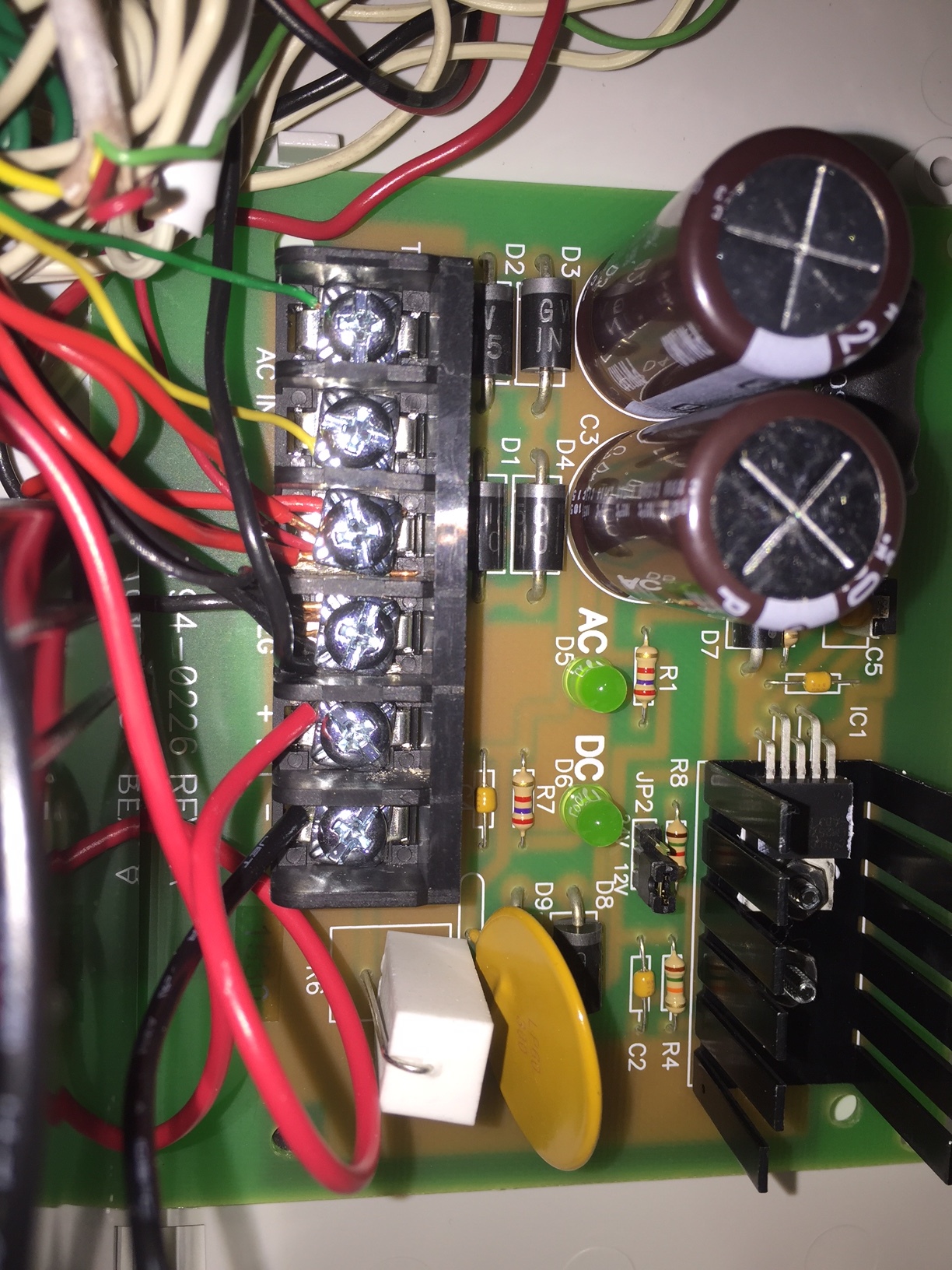
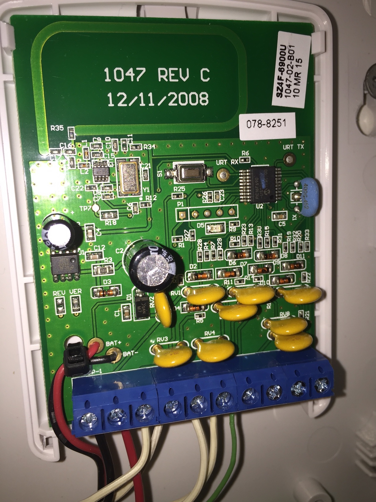
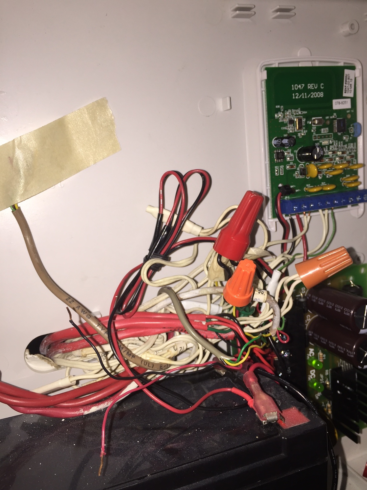
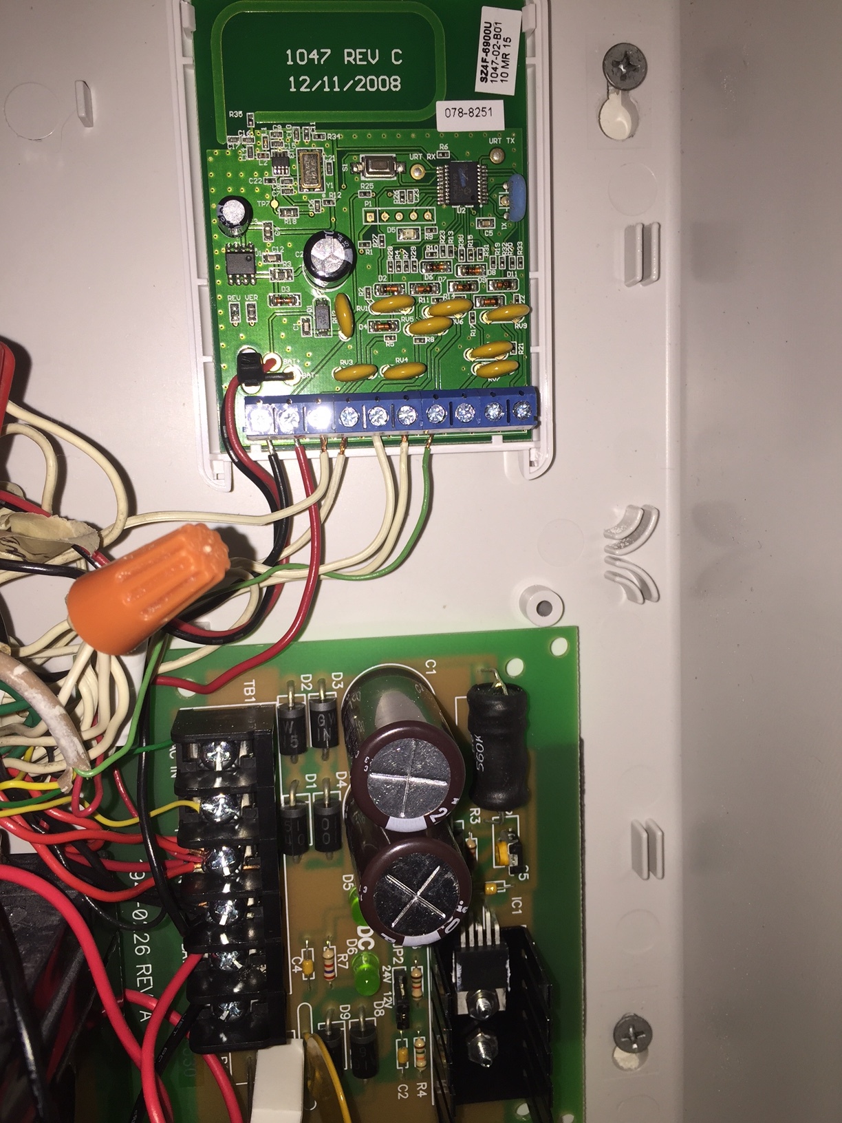
I only have one physical wire into each of the takeover module terminal. Was able to get some pictures sooner. Let me know what you think?
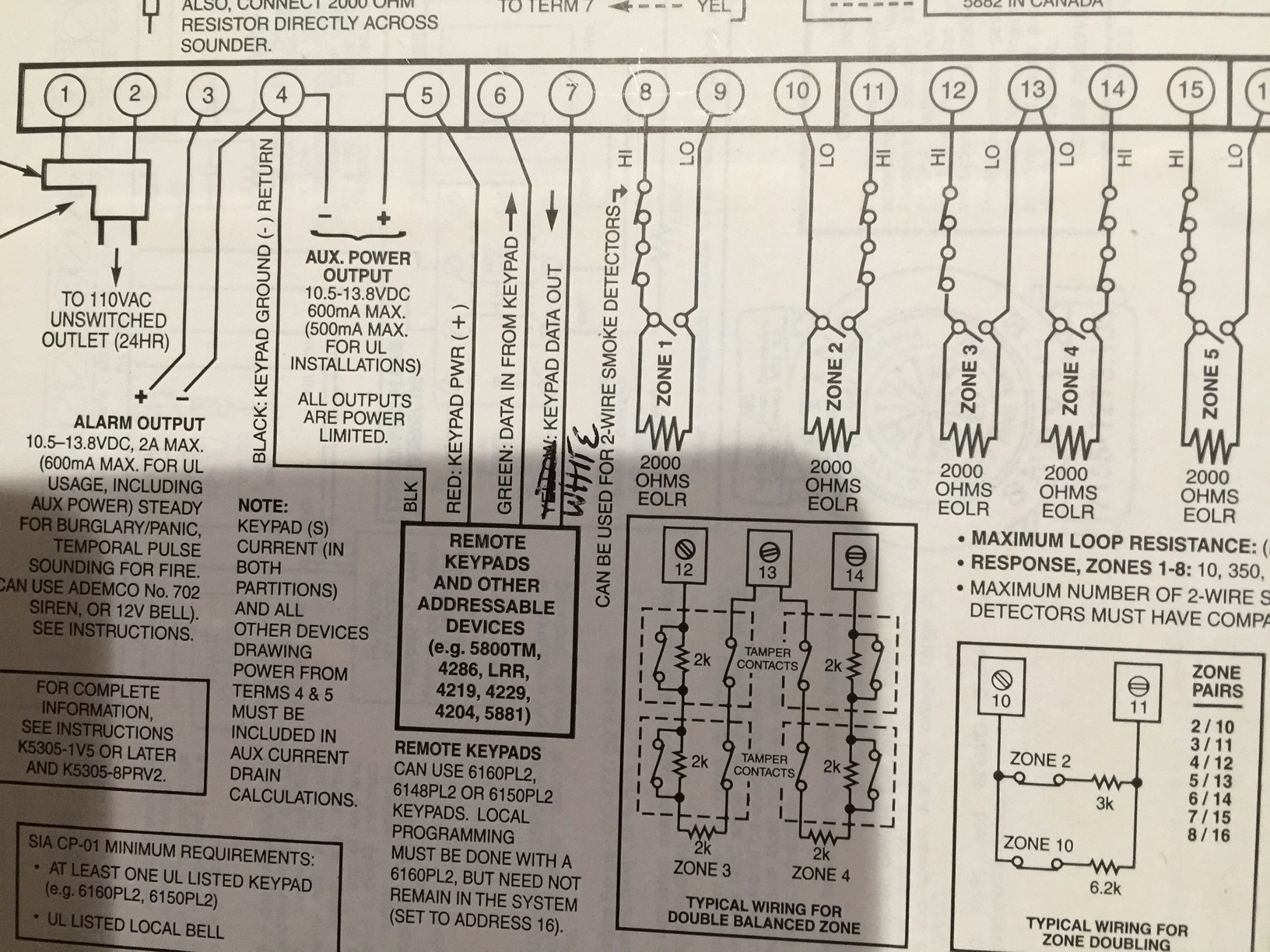
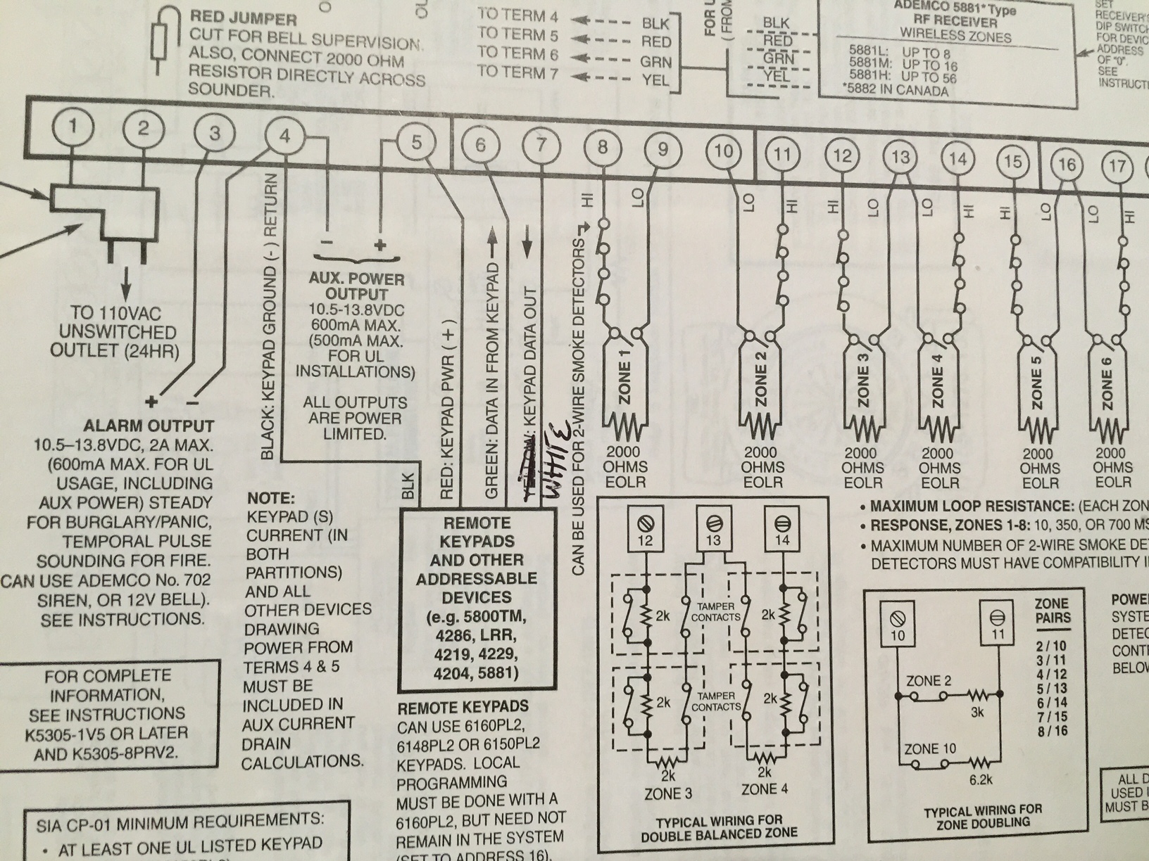
Hard to tell from the picture, but when you say all the “Lo” wires are twisted together, do they physically connect to the Ground on the Take-345 in some way? They would need to either be connected together with a jumper running to G on the Take-345, or twisted together and connected to the DC negative terminal on the power supply board (where the G on the Take also connects)
That right, the red cap includes all the Lo wires for the 5 zones, the motion ground, a ground wire from the Take-345 module and a (-) DC wire twisted together.
Do you have the wires labeled or can you remove the hi and lo from one zone and test resistance?
Using a multimeter, connect the two ends of the circuit to the leads with the sensors closed. Verify it reads 0 or almost 0 ohms. Then open one of the sensors on the circuit, door or window, and verify you see the circuit open. Resistance will increase to infinite ohms, (what the multimeter would read if you turned it on to measure resistance and just held the leads away from each other not touching anything.)
Barring that, I would recommend removing the wires, take one zone’s hi and lo wires and connect to one of the inputs on the module and the lo directly into the G terminal along with the negative 12v power wire. Leave everything else disconnected.
Ideally use a zone with the fewest sensors, something like the entry zone with a couple doors. Just test that zone alone and verify functionality.
One possibility is having hi and lo wires mixed up, with the two ends of one circuit either wired both to Ground or both to inputs, which would leave zones open and unable to close. (It looks like only one zone is currently reporting closed from what I can tell.)
I came home yesterday and the zone for the entry doors (zone 1) was working just fine along with the motion detector. I was also able to add a Honeywell glass break sensor with no issue.
That leaves me with 3 zones for mostly windows that are listed as open. I couldn’t find my multimeter, but switched the hi and lo wires for the missing zones and that didn’t work. I also moved the sensor ground to the module terminal to isolate it. Will try to measure this weekend to confirm the ohms.
but switched the hi and lo wires for the missing zones and that didn’t work
Switching would not change anything, but on many old alarm panels, hi and lo or zone and common terminals are not every other terminal. Usually they are set up like “Zone, Common, Zone, Zone, Common, Zone, Zone, Common” so unless labeled it can be easy to mix one up.
There are a couple possibilities to explore first:
The “hi” for two different zones was accidentally used for the “hi” and “lo” of a single zone. This would make it so the zones could never close.
Resistance may be above the threshold for the Take (3K ohms). It’s possible that wired window sensors may have EOL resistors wired in series at the sensor. A multimeter would be able to verify this.
Hey Jason, I tested the resistance and they did not come back with any feedback. It could be a wire grouping issue. Zones 1 and 5 were tested and came back fine. They work as usual. I suppose I need to hire someone to help at this point.
If you know where the sensors are for the circuits you could test them. If there are any Glass breaks or motion detectors in the home that are wired into those circuits it would be easy to open those and check to make sure no wiring was cut or loose.
I’m not sure how long you used the wired system prior to this, but I have seen in some cases prior owners will have installed a system, noticed a lot of false alarms on a zone (usually a glass break or motion detector) and just remove the wires inside the device, rendering the circuit open and inoperable. Often the zone just gets deleted and forgotten. So if you have moved in recently there may just be some deactivated zones.
Do you know for sure that all the zones and sensors on them worked prior to removing the wires? If so, that can help narrow down likely problems.
That’s correct. I did not find the wires at the panel for the existing zone 1. But zone 2 which is the new zone one (entry doors) works fine. I inherited the system with the home.
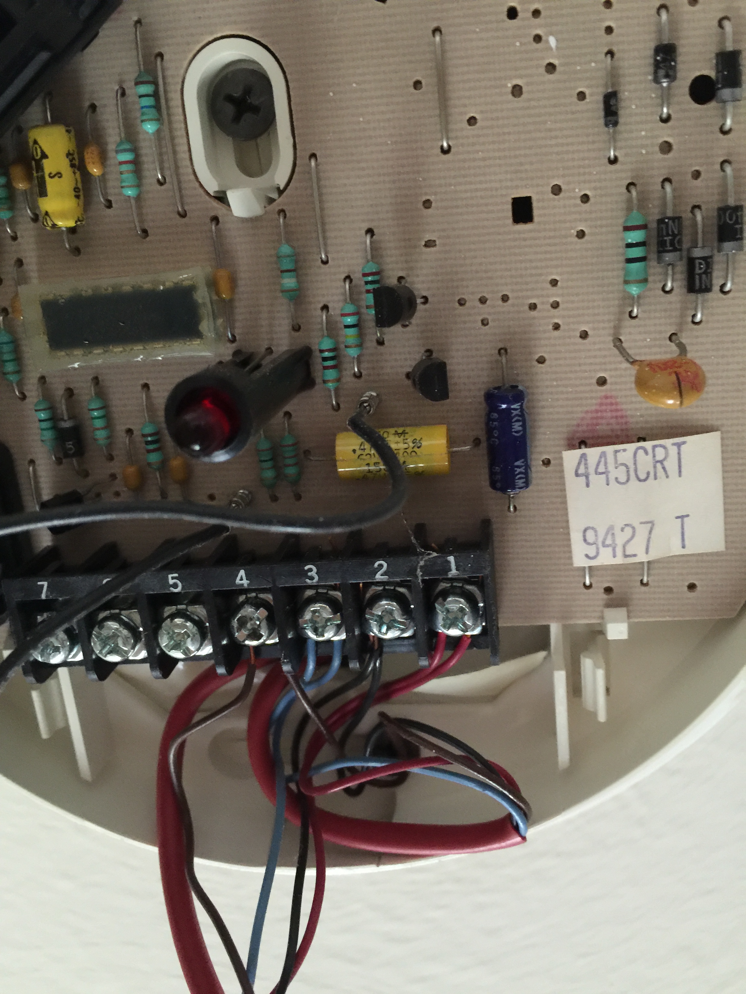
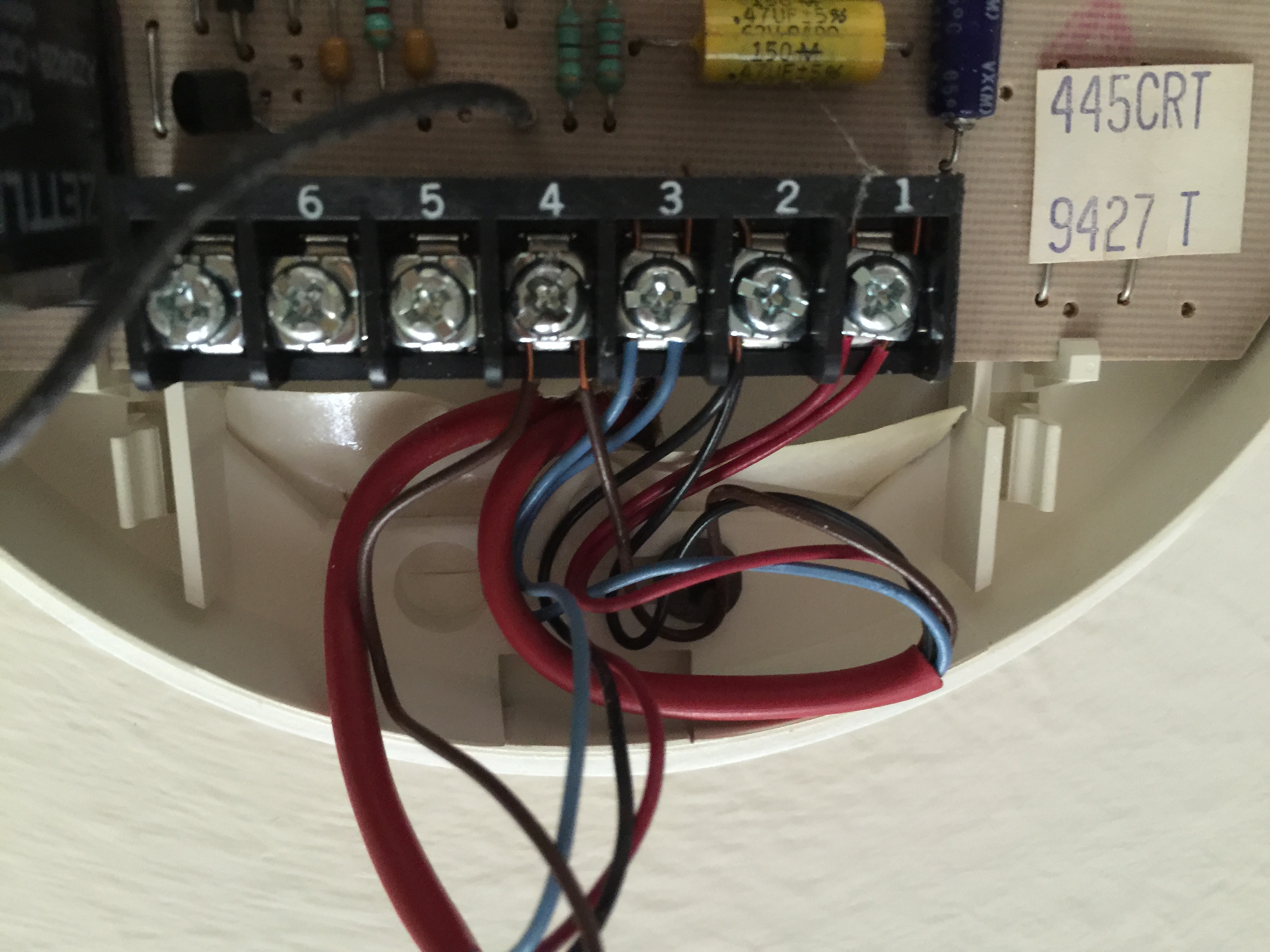
Revisiting this issue with new information. I have found the fire alarm that was originally connected to the alarm. I am enclosing pictures of this old fire alarm detector. I see they cut these sites at the old panel box and put it aside. Two browns and two blue lines are in terminal 3 and 4 of the dectector. What should I do in order make sure that the zone is closed correctly?