Still having an issue with this. I attached it like you told me and now I am getting 13.5ish volts across trigger + and - when the alarm goes off. So that seems correct. Then between NEG and NO I am getting 15.3ish volts but the strobe still isnt going off. Just to be sure I didnt fry the thing, I hooked the strobe straight to the transformer and it is still working. I have a 2 amp 12vdc transformer powering this setup. I cant imagine the amperage would be getting cut right?
Then between NEG and NO I am getting 15.3ish volts
Is this a typo and you mean 13.5?
If not, you’d be exceeding the strobe’s operating voltage.
Have you double checked your polarity for the strobe wires when attaching to the RBSNTTL?
No, it wasnt a misprint. It actually is 15volts for some reason. Dont know where the extra is coming from however. I currently have the positive of the strobe going to NO and the negative to NEG. Now at one point I had attached the positive of the strobe to the NO on the POS side of the board and when I tested between negative and NO it was actually reverse polarity.
Is my jumper set up correctly in the picture?
Is my jumper set up correctly in the picture?
I don’t see anything wrong with it.
No, it wasnt a misprint. It actually is 15volts for some reason.
Very weird, ok. I’m matching your setup here for a test and I am not seeing the same thing. roughly 12VDC off of the relay.
Try testing between the Pos + and Neg - terminals. What is the voltage?
Try testing between the Neg - and the NC terminals. What is the voltage?
Is it at all possible to call you about this? Its going to be hard to describe what I am seeing in text. Bizarre, very bizarre.
suretyDIY Tech support is handled on our forum here. Please let us know what you see for the voltage readings (and any observations that might apply). Photos and links we’ve found far outperform phones - to an amazing degree.
The rear of your RBSNTTL isn’t touching anything conductive while you are testing is it? Make sure to use the self adhesive double stick pads that come in the box to mount it so that nothing can press against the back side of the RBSNTTL.
No the rear of the relay is not touching anything.
Ok, here goes. These readings are in the un-alarmed state.
Trig+ to Trig - = .212v
POS to NEG = 12.31v
NEG to NO = -14.25v
Ok this is where it gets even weirder. If I unplug the NO (Positive strobe wire) and test from NEG of the relay to the disconnected wire I still get -14.25v.
So obviously, I said crap the strobe is powered somehow. I tested just the positive and negative strobe wires completely disconnected from the relay and got 0v.
This is just bizarre.
NEG to NO = -14.25v
What is the voltage reading between Neg- and NO when the strobe is completely disconnected?
Its 0
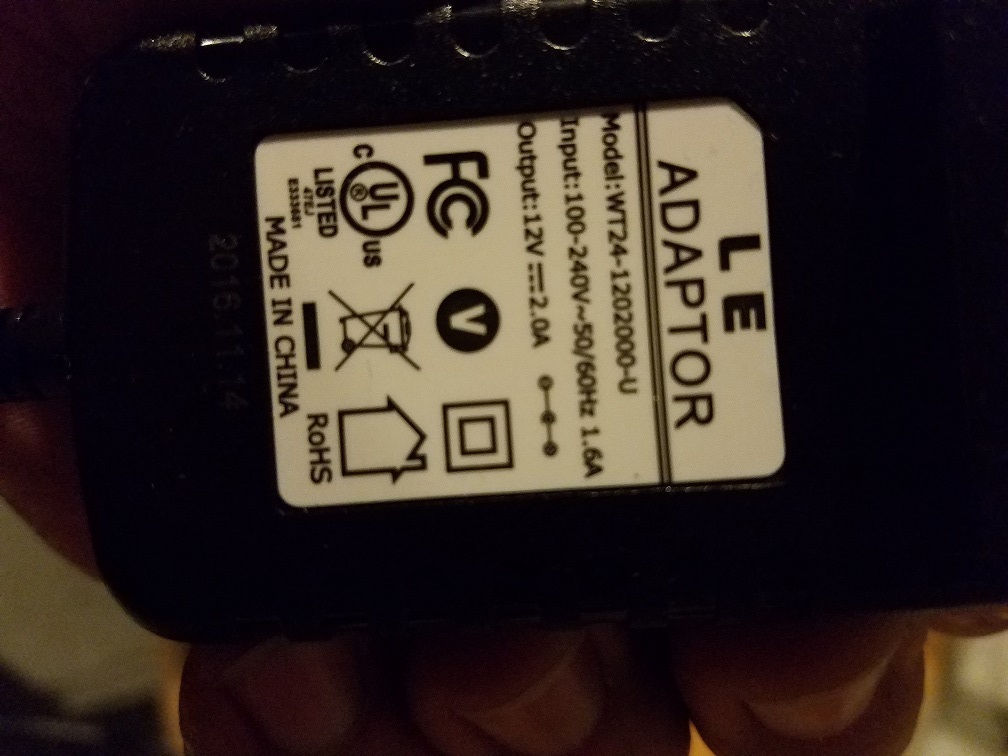
Could you post an image of the 12 V transformer label?
Alright, so we are seeing unexplained reverse polarity voltage readings when the strobe is connected only to NEG -. It works directly off the power supply, but we are seeing excess voltage when the relay is thrown.
Have you tested the NEG- and NO during Alarm but without the strobe attached? What voltage do you see?
I am getting nothing at either NO on the relay.
Across the trigger + and - I get 13.72v with the alarm active.
I am getting nothing at either NO on the relay.
Just to be clear here are the terminals as labeled:
Row 1: Trg- | Pos+ | C | NC | NO
Row 2: Trg+ | Neg- | C | NC | NO
Let’s leave the strobe completely removed.
Your image shows Trg+ and Trg- wired up. Pos+ and Neg- to the power supply. You are seeing appropriate voltage at Pos+ and Neg-. The image shows Pos+ jumped to Row 2 C.
Now, if you apply a trigger voltage (during alarm) and test between Row 2 Neg- and Row 2 NO you should see roughly the exact same value as between Pos+ and Neg-.
When the system is not in Alarm state, test between Row 2 Neg- and Row 2 NC. What voltage do you see? (you should see the same as Pos+ and Neg-)
If you see 12VDC between Neg- and Row 2 NC when the system is not in an alarm state, but do not see it between Neg- and NO when it is in an alarm state, that means the relay is not throwing for some reason.
If you do not see 12VDC between Neg- and Row 2 NC when the system is not in an alarm state, something else is wrong. (flipped polarity, wiring short, bad relay, etc.)
Ok, I am thinking this thing is dead. I have tried it six ways to Sunday and its not doing anything like it should. Do you hear an audible click on yours when the relay switches?
Thank you very much for your help on this. I really appreciate it.
When the system is not in Alarm state, test between Row 2 Neg- and Row 2 NC. What voltage do you see? (you should see the same as Pos+ and Neg-)
Can you test the above and let us know what you see? Is that also 0?
It is entirely possible it is a bad relay, but you’ll want to be certain.
I can say I am testing using a GC3, an RBSNTTL, and a 12VDC Power supply, with the trigger being thrown by the open collector.
If I measure across row 2 negative and NC in disarm state I get 12.3v. In the arm state I get nothing.
That’s good, that means common and NC are working properly.
Just to clarify, you tested between Neg and NC during alarm state as well and got 0? But Neg and NO also shows 0 in alarm state? That would indicate the relay is not switching fully, and is likely a defect.
Can you try jumping POS to row 1 C and using the Row 1 NO instead? Does that work?