I wired up my system like figure 1 on the superswitch manual. The reason why I did this was because my existing panel had more than 8 zones and they had resistors on every zone and looked like some were in series. I was told I could cut the resistors off and just hook all the common together and the others in the superswitches. I have everything powered by the panel and hook up the battery and then power and everything comes on at the same time.
Unfortunately I haven’t been able to get anything working on the superswitches, when I power up the superswitches without anything connected the red LED light comes up, as soon as I connect something the red led light is off. I have even just tried to get one thing working and no luck.
I am at a loss as to what to try next, unfortunately I don’t have my multi-meter to check the wires though it was all working when it was hooked up to the vista panel.
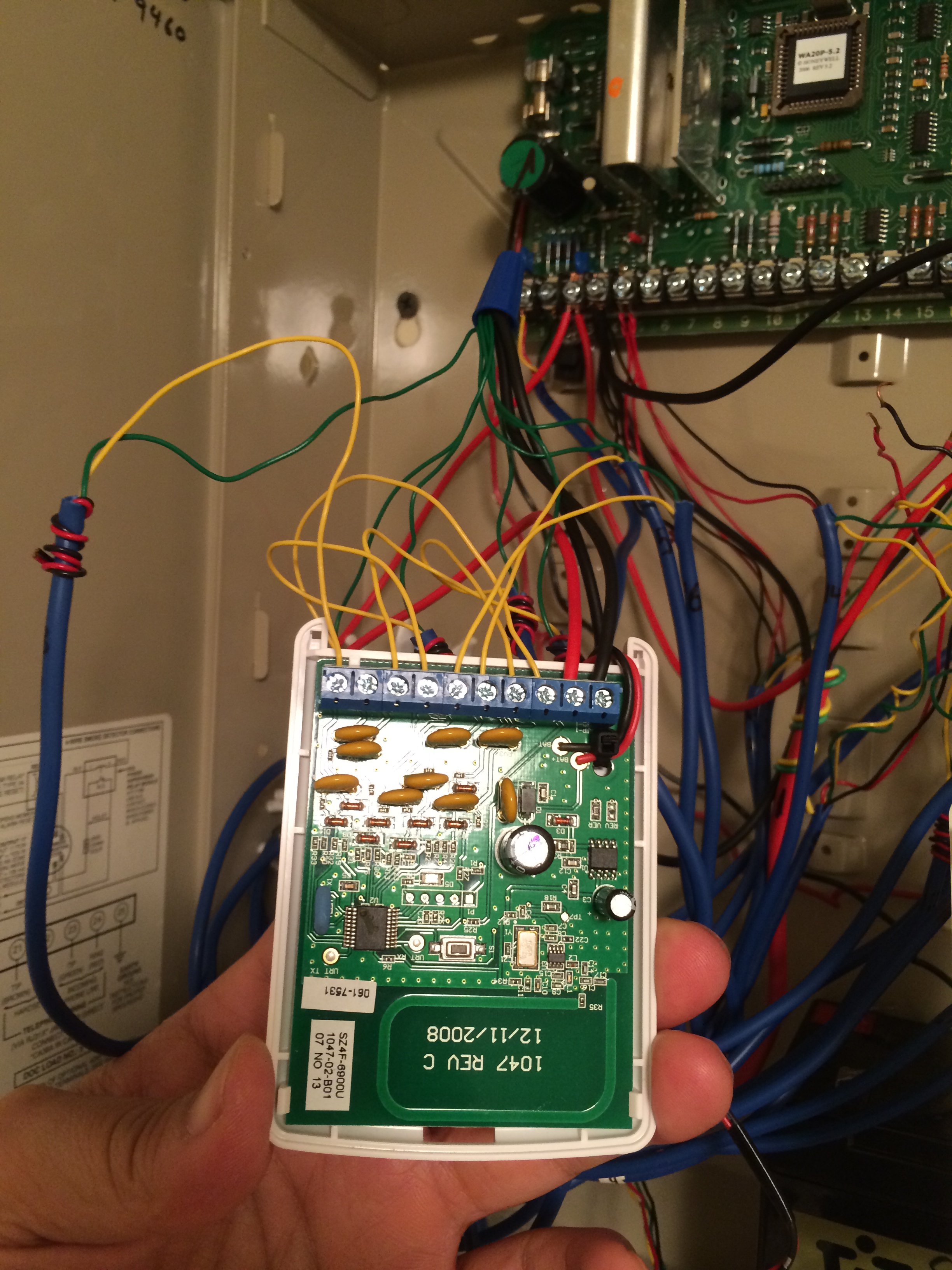
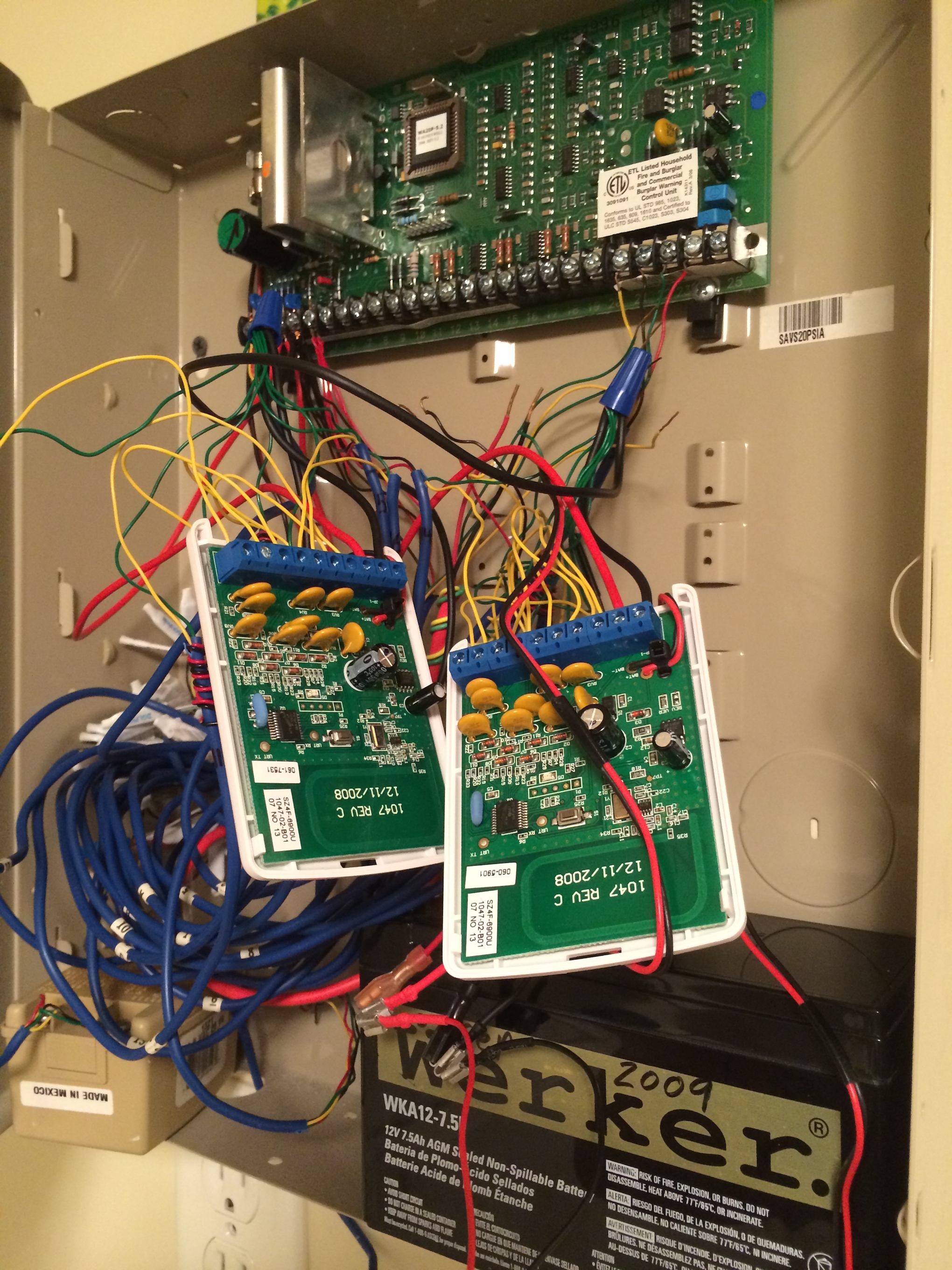
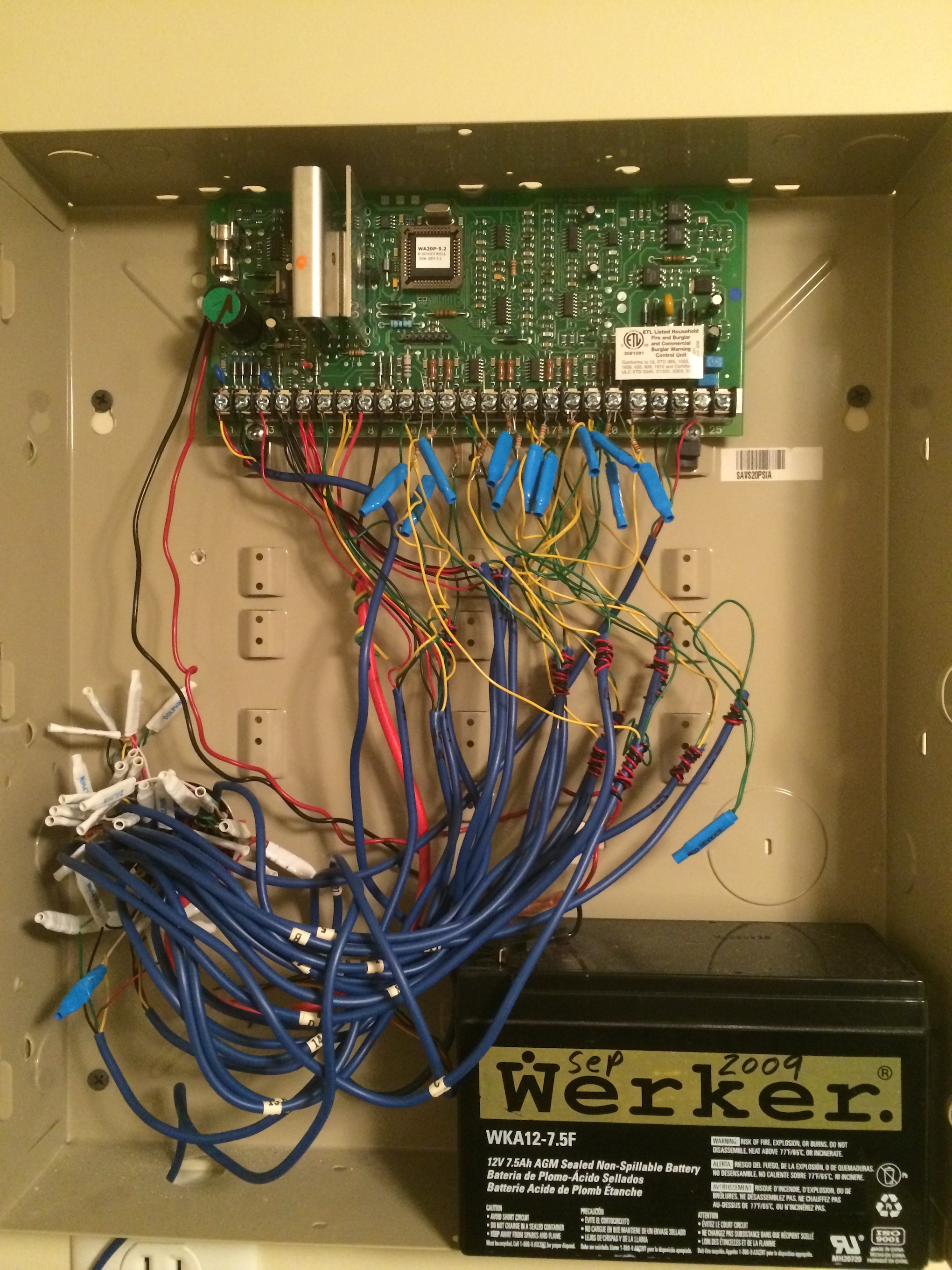
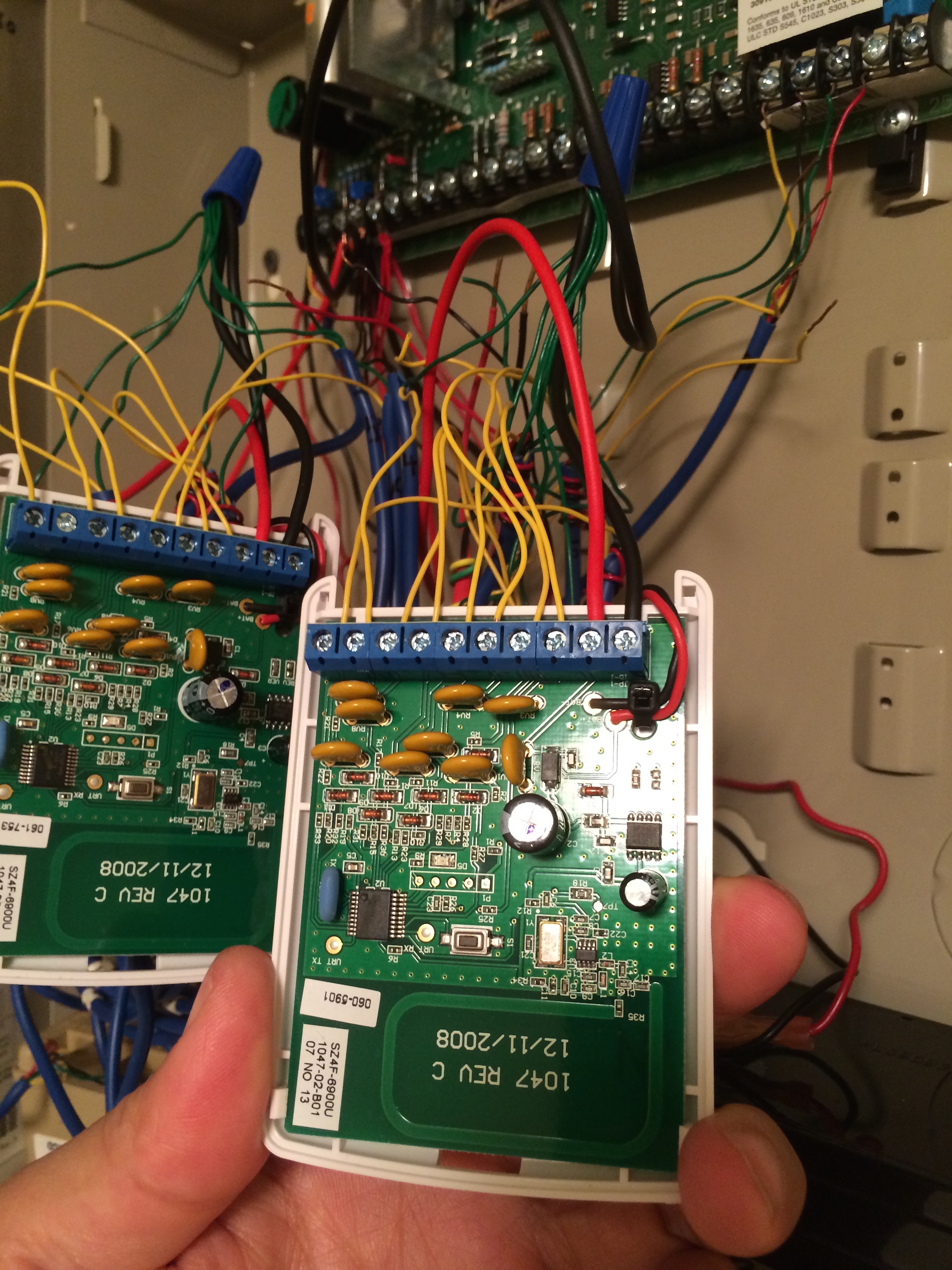
Can you take a good, clear photo of how you have it wired now and attach it to your post?
Yes, you can get rid of the resistors. The super switch works fine without an EOL resistor in the loop. If your old panel has more than 8 zones (you must have a Vista expansion module?) then you’re going to have to combine some zones by wiring them together in series to reduce it down to 8 zones, or you could get an additional super switch for the extra zones.
If you get in trouble, one method that might help is to use 8 jumper wires to connect each zone input on the super switch to ground (G) on the super switch. Then power up the super switch and verify that all zones are showing as closed on the 2GIG panel. Then disconnect zone 1 and verify that it shows zone 1 is open on the 2GIG panel. Then reconnect zone 1 and disconnect zone 2 and verify that zone 2 is open on the 2GIG panel. Repeat for all 8 zones. If they work then you know the super switch and panel programming are fine and the problem is with your sensor wiring. At that point you can work on 1 zone at a time, leaving the other 7 jumper wires in place so those other zones stay closed on the 2GIG panel.
If you own a multimeter then I would recommend having it by your side when doing this kind of work. Wiring electronics with a multimeter is like driving blindfolded.
Sure, I don’t have it wired to the backup power or plugged in.
The panel didn’t they did some thing to get more zones that was what was the confusing thing I will attach a pic of how they had it wired up originally.
So my newbie quesiton is I can’t find how to see the status of the superswitch on the panel? I can only see it from alarm.com
Will get back to you on the test.
Unfortunately its a 4 hour round trip for just the multimeter.
After looking over the pictures you sent and looking over a Vista 20P wiring schematic I think I may have figured out what the problem is. It looks like you have the power wire going from the 12V+ terminal on the superswitch to the + Alarm output terminal (terminal 3) on the Vista 20P. It needs to be going to the + Aux Power terminal (terminal 5) on the Vista 20P.
While they both produce the same level of voltage, the Alarm terminals will only provide the voltage when the system triggers an alarm state. The Aux terminals will provide constant voltage. If you move the power wires from terminal 3 to terminal 5, that should solve your problem.
The first way would be to see if the light on the green LED on the home button is turned on. If it’s not, then something is open. Additionally, the “Security Button” on the home screen will be yellow and you should have text along the top of the touchscreen telling you exactly which sensor is open.
Another way to check would be to press the System Status button on the touchscreen to tell you all the sensors that are open.
Is there a way to disable a sensor or do you have to delete it?
Also any tips on troubleshooting a sensor/line that isn’t working. I have checked that its not the sensor as I change it out to one that works and tested so both sensors work.
Thanks Ryan, I have everything but the one door sensor that I need to get my multimeter to see what is going on, I did get a magnet to see if it was the magnet though no luck there.
I know the super switch is good as I jumped them all to make sure they would sound.
If you know the super switch is working then you can use it as a continuity checker and maybe not need the multimeter. If you have the cable properly wired to the super switch, disconnect the cable from the sensor and make sure those exposed wires at the sensor end aren’t touching each other - then the 2GIG panel should show the zone as open. If you take the exposed wires at the sensor end and clip or twist them together so they’re touching then the 2GIG panel should show the zone as closed. If both of those tests worked correctly then your cable is good. If either of those tests fails then something is wrong in the cable. At that point a multimeter would be useful to see if there is any unexpected resistance in the cable.
A ring tone generator might also be useful to make sure you’re working with the right cable at the super switch end, although at that point it might be cheaper just to use a wireless sensor there.
Also, is it possible that cable goes to more than one sensor and it’s disconnected at the other sensor’s location? I know I’m reaching here but if the zone worked on the Vista panel then it should work on the super switch. We must be overlooking something.
So I broke down and bought another multimeter, the cable is broke somewhere. I checked all 4 wires and put them all together and no luck, looks like I will be buying a wireless sensor for that door.
I have one more question I have two roller sensors on my french doors, but they only register when one side is open. I can open the other side and it wont trigger. It looks like they are wired in parallel, though I was wondering if I wire it in series if any of the sensor trips it will send a signal correct?
Security alarm sensors are normally closed sensors. With normally closed sensors, wiring in parallel is a logical “and” operation and wiring in series is a logical “or” operation. So if they were wired in parallel then the zone would trigger only when both the left “and” right door were opened. If they were wired in series then the zone would trigger if either the left “or” right door were open. For security, they should be wired in series because if they were wired in parallel then a bad guy could just open one door and walk in without being detected. If yours are wired in parallel then whoever installed them made a mistake.
Neither series nor parallel explain why one side would trigger the alarm but the other wouldn’t. It sounds like the sensor on the side that isn’t working is shorted. I’ve seen that happen most often when a sensor isn’t working but instead of replacing it the technician just shorts (connects) the wires across the faulty sensor to bypass it. Is that maybe what you’re seeing? If so, that’s bad for security too.
It has to be wired in parallel or they did something down at the box, as right now when I open one door it doesn’t chime, though if I open the other door it chimes and then when I push the sensor on the door opened first it chimes too. The first thing I did after it didn’t chime was to check and switch the sensors to make sure they both worked.