I’m installing a “2GIG Switch To Surety Kit” later today. Is the alarm system config (list of door/window sensors, Zwave devices, etc.) all stored in the panel such that once it connects to alarm.com that it will populate their website? Or do I need to write down the config from the panel before I perform the cutover?
I’m installing a “2GIG Switch To Surety Kit” later today. Is the alarm system config (list of door/window sensors, Zwave devices, etc.) all stored in the panel such that once it connects to alarm.com that it will populate their website?
Yes that is correct. Updating the firmware and installing the new cellular module into a 2GIG Go!Control would not remove sensor programming stored in the panel.
Additionally, once your Alarm.com account has been created and you run a cell test at the panel to connect to Alarm.com, sensor programming etc, would be passed to the Alarm.com shortly after the cell test has been run.
I’m currently flashing the firmware on the CP2. I also have a TS1 secondary panel. Is it OK to flash the TS1 same way, using the TS1 file of course, before I swap in the LTE board?
Its probably best to do it before you swap to the LTE module and get connected but you can flash the TS1 before or after you add the module to the main panel.
The TS1 just wont connect to the Go!Control until its at FW 1.16 (1.16 is currently the highest firmware for the TS1 and is compatible with all FW from 1.16 to current on the main panel).
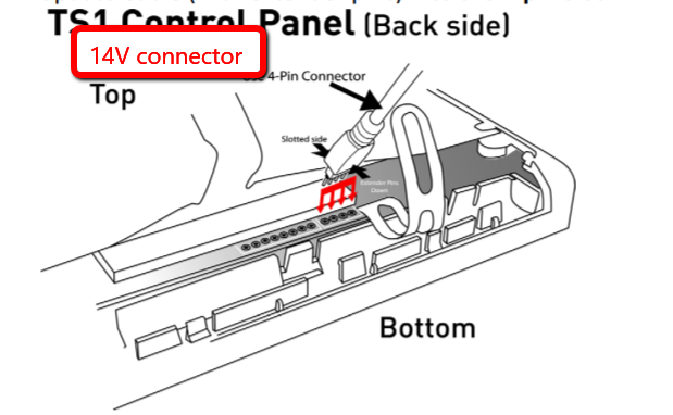
Be sure to use the included 4-pin connector. This guide will help with updating the TS1 as the cable doesnt fit in as snuggly on the TS1 as it does on the Go!Control and the guide has some helpful pictures.
Tyler- I just want to double check the cable position for the TS1 upgrade. When the TS1 is hanging by the “third hand”, the bottom of the TS1 where the 4 pin connect is closet to the wall. Hope that makes sense. This note is a little unclear to me:
WARNING: When inserting the Firmware Update Cable (with the extender pins) it is EXTREMELY IMPORTANT to insert the cable with the flat side DOWN and the slotted side UP.
To clarify, should the slotted side of the connector face the TOP of the unit, or one could say the slotted side should face the 14V connector, or you could also say the flat side should face the wall and the slotted side should face away from the wall as it’s hanging from the “third hand”?
Thanks-
Mark
Please disregard, I figured it out. After reading the instructions a couple more times, and letting it sink in, then I hooked up the cable correctly. When I ran the update, I discovered the TS1 was already at the required firmware level. Haha!
1 Like
I was just about to reply. Nice work!